
Injection apparatus and injection method for liquid sample for standard gas production

a technology of liquid sample and injection apparatus, which is applied in the direction of sampling, measurement devices, instruments, etc., can solve the problems of increasing the cost of manufacturing the device by such treatment, the risk of damaging the rubber septum used for sealing, etc., and achieves the effect of increasing the cost of manufacturing the device, improving the durability of the device, and increasing the cost of production

Active Publication Date: 2019-07-25
KOREA RES INST OF STANDARDS & SCI
View PDF8 Cites 0 Cited by
  • Summary
  • Abstract
  • Description
  • Claims
  • Application Information

AI Technical Summary

Benefits of technology

The present invention provides a device that prevents liquid samples from adsorbing to the injection apparatus or being left in it. This is achieved through a structural improvement of the device that minimizes the region where the liquid sample comes into direct contact with the injection apparatus. This avoids the need to heat the liquid sample to volatize it and prevents damage to the device. Additionally, the special coating treatment that was conventionally used to prevent liquid samples from being left is eliminated, resulting in cost savings.

Problems solved by technology

However, in a process of volatilizing a left liquid sample using heat as in the related art document, when a heating temperature is excessively increased, there is a risk of damaging a rubber septum used for sealing.
In addition, in order to minimize the extent to which the liquid sample is deposited inside the needle, a surface of the device was subjected to special coating treatment, but there was also a problem that the cost of manufacturing the device by such treatment is increased.

Method used


Image

  • Injection apparatus and injection method for liquid sample for standard gas production
  • Injection apparatus and injection method for liquid sample for standard gas production
  • Injection apparatus and injection method for liquid sample for standard gas production

Examples


Embodiment Construction

[0028]

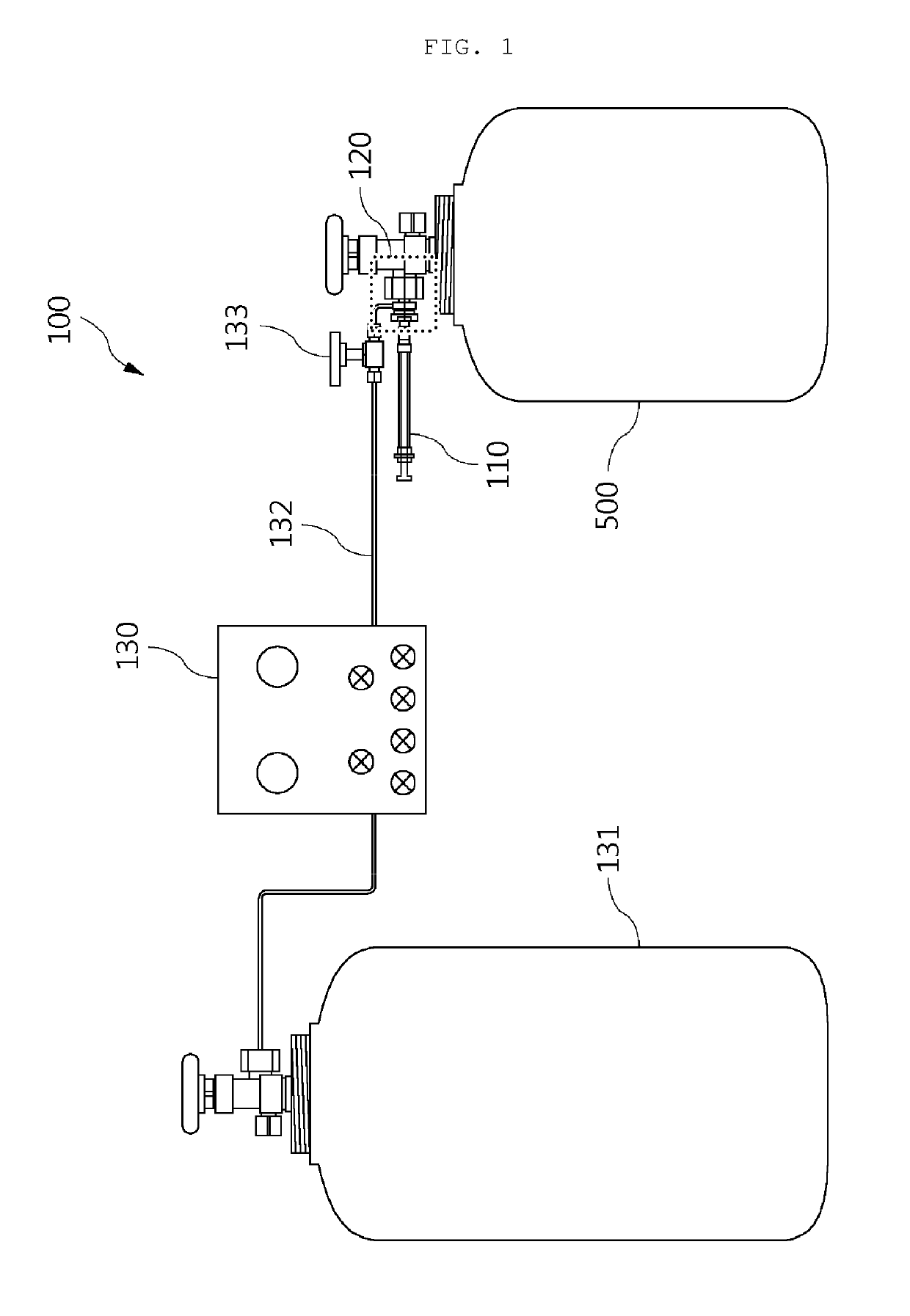
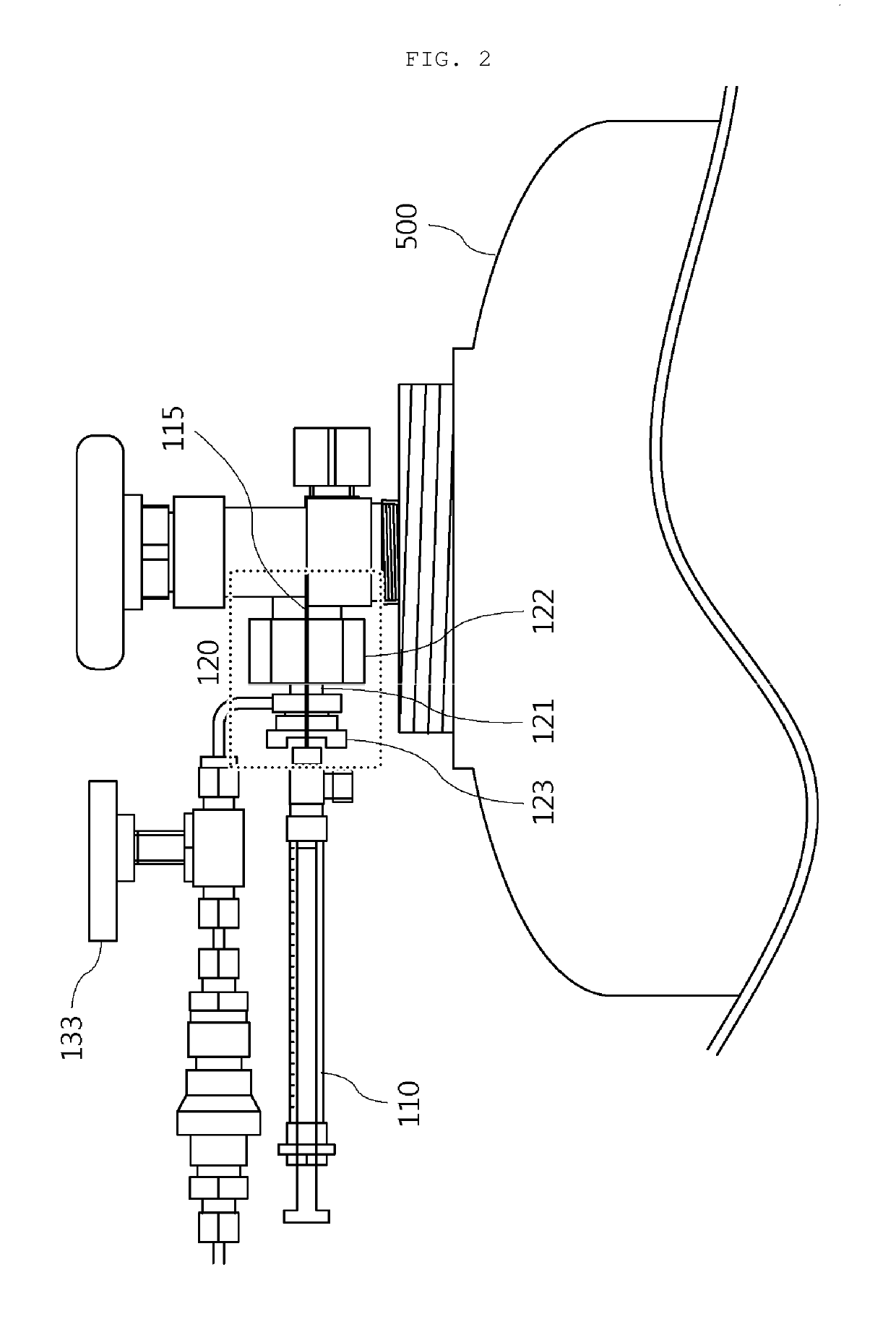
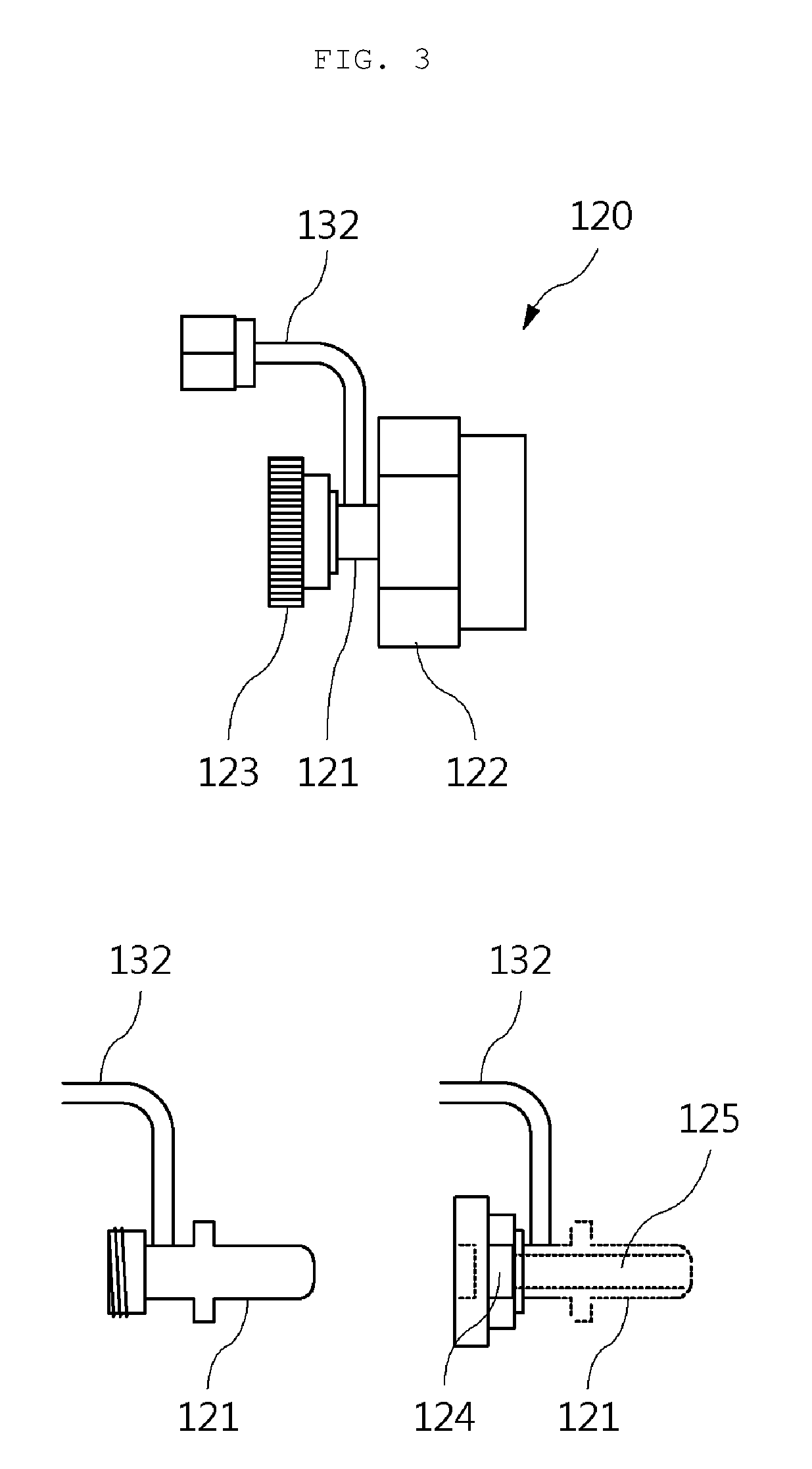
100: liquid sample injection apparatus110: syringe115: needle115a: discharge hole120: liquid injection part121: body part122: container connection part123: syringe connection part124: septum125: penetration path130: standard gas preparation device131: diluted gas cylinder132: gas transfer passage133: control valve

BEST MODE

[0029]Hereinafter, a liquid sample injection apparatus and injection method for preparation of standard gas according to the present invention having the configuration as described above will be described in detail with reference to the accompanying drawings.

[0030]FIG. 1 is a configuration view of a injection apparatus for liquid for standard gas production according to the present invention. In addition, FIG. 2 is an enlarged view of a liquid injection part, FIG. 3 is a detailed exploded view of the liquid injection part, and FIG. 4 is an enlarged view of a syringe. A configuration of a injection apparatus for liquid for standard gas production according to ...


PUM

PropertyMeasurementUnit
massaaaaaaaaaa
temperatureaaaaaaaaaa
melting propertyaaaaaaaaaa

Abstract

The purpose of the present invention is to provide an injection apparatus and an injection method for a liquid sample for standard gas production, wherein the injection apparatus for injecting a liquid sample present in a liquid state at room temperature into a standard gas container has an improved structure that minimizes the area in which the liquid sample directly contacts the injection apparatus so as to prevent the problem in which the liquid sample is adsorbed into the injection apparatus. Furthermore, another purpose of the present invention is to provide an injection apparatus and an injection method for a liquid sample for standard gas production, in which a step of volatilizing the remaining liquid sample by heating is eliminated during the injection of the liquid sample, thereby preventing the apparatus from being damaged by heating to thereby improve the durability of the apparatus.

Description

CROSS-REFERENCE TO RELATED APPLICATIONS[0001]This application is the 35 U. S. C. § 371 National Stage patent application of International Application No.: PCT / KR2018 / 007951, filed Jul. 13, 2018, entitled, INJECTION APPARATUS AND INJECTION METHOD FOR LIQUID SAMPLE GAS PRODUCTION, the entire disclosure of which is herein incorporated by reference.TECHNICAL FIELD[0002]The present invention relates to a liquid sample injection apparatus and injection method for preparation of standard gas, and more particularly, to a liquid sample injection apparatus and injection method for preparation of standard gas that minimizes a problem that a liquid sample is adsorbed to the injection apparatus by improving a conventional structure, in the injection apparatus for injecting the liquid sample that exists in a liquid state at room temperature into a standard gas container.[0003]A reference material is a substance that may become a standard as a chemical species, similar to a prototype in a meteorol...

Claims


Application Information

Patent Timeline
Patent Type & Authority Applications(United States)
IPC IPC(8): G01N1/38G01N33/00B01L5/02
CPCG01N1/38G01N33/0018B01L5/02G01N2001/387G01N2001/2893G01N2001/386G01N33/0011
Inventor KANG, JIHWANKIM, YONG DOOLEE, SANGIL
Owner KOREA RES INST OF STANDARDS & SCI
Learn More