Unlock instant, AI-driven research and patent intelligence for your innovation.

Weatherization system for a wellhead emission reduction system

a technology of wellhead and emission reduction system, which is applied in the direction of sealing/packing, wellbore/well accessories, separation processes, etc., can solve the problems of system venting or leaking to a point, and affecting the quality of wellhead

Active Publication Date: 2019-08-01
ETTER ENG
View PDF2 Cites 0 Cited by
  • Summary
  • Abstract
  • Description
  • Claims
  • Application Information

AI Technical Summary

Benefits of technology

The patent describes a weatherization system for controlling methane emissions from a wellhead. The system includes a housing, a catalytic heating assembly, and a stack assembly. The stack assembly prevents weather or atmospheric factors from entering the housing and includes a stack adapter with a sloped region to prevent accumulation of weather. The system also includes a stack cover that facilitates exhaust flow out of the housing. The use of weather-resistant materials and techniques helps to reduce the effects of weather or other atmospheric factors on the system. Overall, the system helps to control methane emissions and minimize damaging effects on the environment.

Problems solved by technology

Methane emissions also result from livestock and other agricultural practices and by the decay of organic waste in municipal solid waste landfills.
Methane is the primary component of natural gas, and is the principal greenhouse gas emitted by equipment and processes in the oil and gas sector; and, through leakage and venting during the process of drilling for oil and gas can have a serious effect on the atmosphere.
While methane doesn't remain in the atmosphere as long as carbon dioxide does, it has far more devastating consequences to the climate because of how effectively it absorbs heat.
Thus, what is not appreciated by the prior art is that regardless of what methodology is utilized to “treat” the vented methane to meet government standards and / or industry expectations, if the system employed is susceptible to maintenance, degradation of effectiveness, or flow-through issues, then the system may actually vent or leak to a point where more harm than good is created by the system.

Method used


Image

  • Weatherization system for a wellhead emission reduction system
  • Weatherization system for a wellhead emission reduction system
  • Weatherization system for a wellhead emission reduction system

Examples


Embodiment Construction

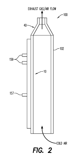
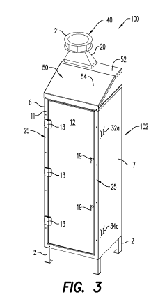
[0011]The present embodiments may be associated with a weatherization system for methane emission control for a wellhead. The system may include a stack assembly that prevents weather or atmospheric factors from entering a housing of the weatherization system. According to an aspect, the stack assembly includes a stack adapter. The stack adapter includes an upper portion, a lower portion to engage the housing, and a plurality of walls extending between the upper and lower portions. According to an aspect, at least one of the plurality of walls has a sloped region that prevents weather or atmospheric factors from accumulating at the upper portion of the stack adapter. The stack assembly further includes a stack cover adjacent the upper portion of the stack adapter. The stack cover forms an exhaust point that facilitates exhaust flow out of the housing.

[0012]The present disclosure may further be associated with a weatherization system for methane emission control for a wellhead, which...


PUM

PropertyMeasurementUnit
interior volumeaaaaaaaaaa
cylindrical shapeaaaaaaaaaa
shapeaaaaaaaaaa

Abstract

A weatherization system for a wellhead methane emission reduction system is described. The weatherization system reduces green-house gas emission into the atmosphere and reduces the effects of weather on the methane emission reduction system. The weatherization system includes a stack assembly connected to a housing of the reduction system by a housing adapter. The stack assembly includes a stack adapter and a stack cover, which collectively helps protect the methane emission reduction system and prevents weather or atmospheric factors from entering the housing. The weatherization system may include one or more sensors for measuring the effects of weather or degradation of at least one of the weatherization system and the methane emission reduction system.

Description

CROSS-REFERENCE TO RELATED APPLICATIONS[0001]This application claims priority to U.S. Provisional Application No. 62 / 623,109 filed Jan. 29, 2018, which is incorporated herein by reference in its entirety.FIELD OF THE DISCLOSURE[0002]A weatherization system for controlling methane emission of a wellhead is described. More specifically, the present disclosure relates to a weatherization system that monitors the operation and / or performance of a catalytic heater assembly included in the system. More specifically, a weatherization system that prolongs the useful life of a methane emission control system for a wellhead, while monitoring the effects of weather or atmospheric factors on the methane emission control system is described.BACKGROUND OF THE DISCLOSURE[0003]Political, scientific and sociological debate over the past twenty years has converged on the topic of global warming and the effects of production and venting of so-called greenhouse gases, or gasses that trap heat in the at...

Claims


Application Information

Patent Timeline
Patent Type & Authority Applications(United States)
IPC IPC(8): E21B33/037E21B41/00B01D53/86B01D53/88
CPCE21B33/037E21B41/005E21B41/0021B01D53/864B01D53/885B01D2257/7025B01D2256/22B01D2255/1021B01D2255/1023B01D2258/06B01D2258/02E21B33/03Y02C20/20
Inventor ETTER, THOMAS M.MOORE, SR., JON G.HANSEN, ALEX
Owner ETTER ENG