Radar device, signal processor, and signal processing method
- Summary
- Abstract
- Description
- Claims
- Application Information
AI Technical Summary
Benefits of technology
Problems solved by technology
Method used
Image
Examples
first embodiment
1.2. First Embodiment
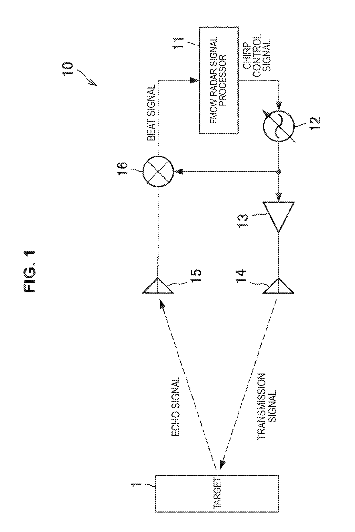
[0071]A first embodiment of the present disclosure is first described. The configuration example of the FMCW TDMA MIMO radar device uses the same configuration as that illustrated in FIG. 5 in describing the first embodiment.
[0072]The first embodiment of embodiments of the present disclosure is intended to eliminate the influence based on the motion of a mark by appropriately setting on and off timings of the switches 131a and 131b by the FMCW TDMA MIMO radar signal processor 110. More specifically, the FMCW TDMA MIMO radar signal processor 110 sets on and off timings of the switches 131a and 131b from the FMCW TDMA MIMO radar signal processor 110 by performing repetitive transmission so that the antenna element numbers of the transmitting array antennas are anterior-posterior symmetrical centering on the reference time.
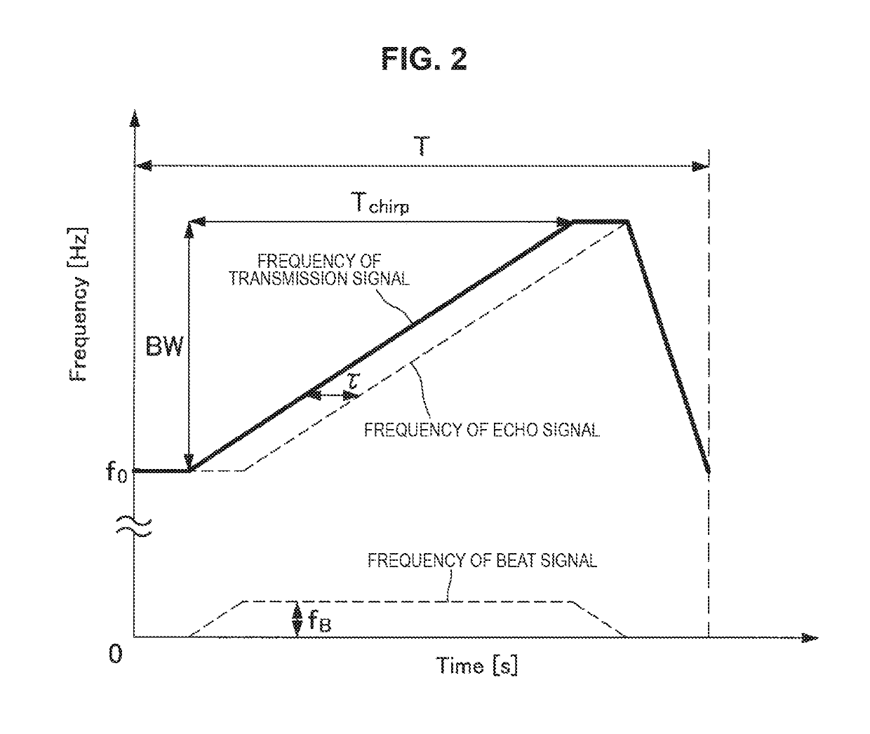
[0073]FIG. 8 is a diagram illustrated to describe the relationship between the chirp by the local oscillator of the FMCW TDMA MIMO radar device ...
second embodiment
1.3. Second Embodiment
[0090]A second embodiment is subsequently described. In the signal processing for removing the Doppler phase that is described in the first embodiment, the beat signals SB1 and SB2 are used as a time signal. However, this signal processing can be performed in the frequency spectrum in a similar way. In the FMCW radar device, it is common practice to convert the beat signal into a frequency spectrum by performing a discrete Fourier transform on the beat signal, so it is very preferable to remove the Doppler phase in the frequency domain.
[0091]In the case of removing the Doppler phase in the frequency domain, the signal processing is performed on the beat signals SB1 and SB2 subjected to discrete Fourier as expressed in Formula 18 below.
[Math. 18]
F[ŜB]=½(|F[SB1|]+|F[SB2|])·exp[j arg(F[SB1]+F[SB2])] (Formula 18)
[0092]FIG. 13 is a flowchart illustrating an operation example of the FMCW TDMA MIMO radar device 100 according to the embodiment of the present disclosur...
third embodiment
1.4. Third Embodiment
[0097]The signal processing described in the first embodiment, in a case where the cosine component of Formula 16 becomes zero, fails to perform the operation for obtaining the angle of Formula 15, so the beat signals at the reference time fail to be synthesized. Thus, in the third embodiment, a third beat signal SB3 is obtained by averaging the first beat signal SB1 and the second beat signal SB2, and the amplitude of the third beat signal SB3 is compared with the amplitude of the first beat signal SB1, so in a case where the amplitude ratio is smaller than a predetermined threshold value (e.g., 1 / 10 or less), the signal processing is not performed.
[0098]FIG. 14 is a flowchart illustrating an operation example of the FMCW TDMA MIMO radar device 100 according to the embodiment of the present disclosure. The operation example of the FMCW TDMA MIMO radar device 100 according to the embodiment of the present disclosure is now described with reference to FIG. 14.
[00...
PUM
 Abstract
Description
Claims
Application Information
 - R&D
- Intellectual Property
- Life Sciences
- Materials
- Tech Scout
- Unparalleled Data Quality
- Higher Quality Content
- 60% Fewer Hallucinations
Browse by: Latest US Patents, China's latest patents, Technical Efficacy Thesaurus, Application Domain, Technology Topic, Popular Technical Reports.
© 2025 PatSnap. All rights reserved.Legal|Privacy policy|Modern Slavery Act Transparency Statement|Sitemap|About US| Contact US: help@patsnap.com


