
Wireless battery management system and battery pack including same

a battery management system and battery pack technology, applied in battery/fuel cell control arrangement, secondary cell servicing/maintenance, high-level techniques, etc., can solve the problems of literature 1 having limitations in the use of electrical energy of batteries, residual capacity deviation often occurs between battery modules, etc., to prevent overdischarge of battery modules, reduce residual capacity deviation, and rapid balancing

Active Publication Date: 2019-08-01
LG ENERGY SOLUTION LTD
View PDF1 Cites 35 Cited by
  • Summary
  • Abstract
  • Description
  • Claims
  • Application Information

AI Technical Summary

Benefits of technology

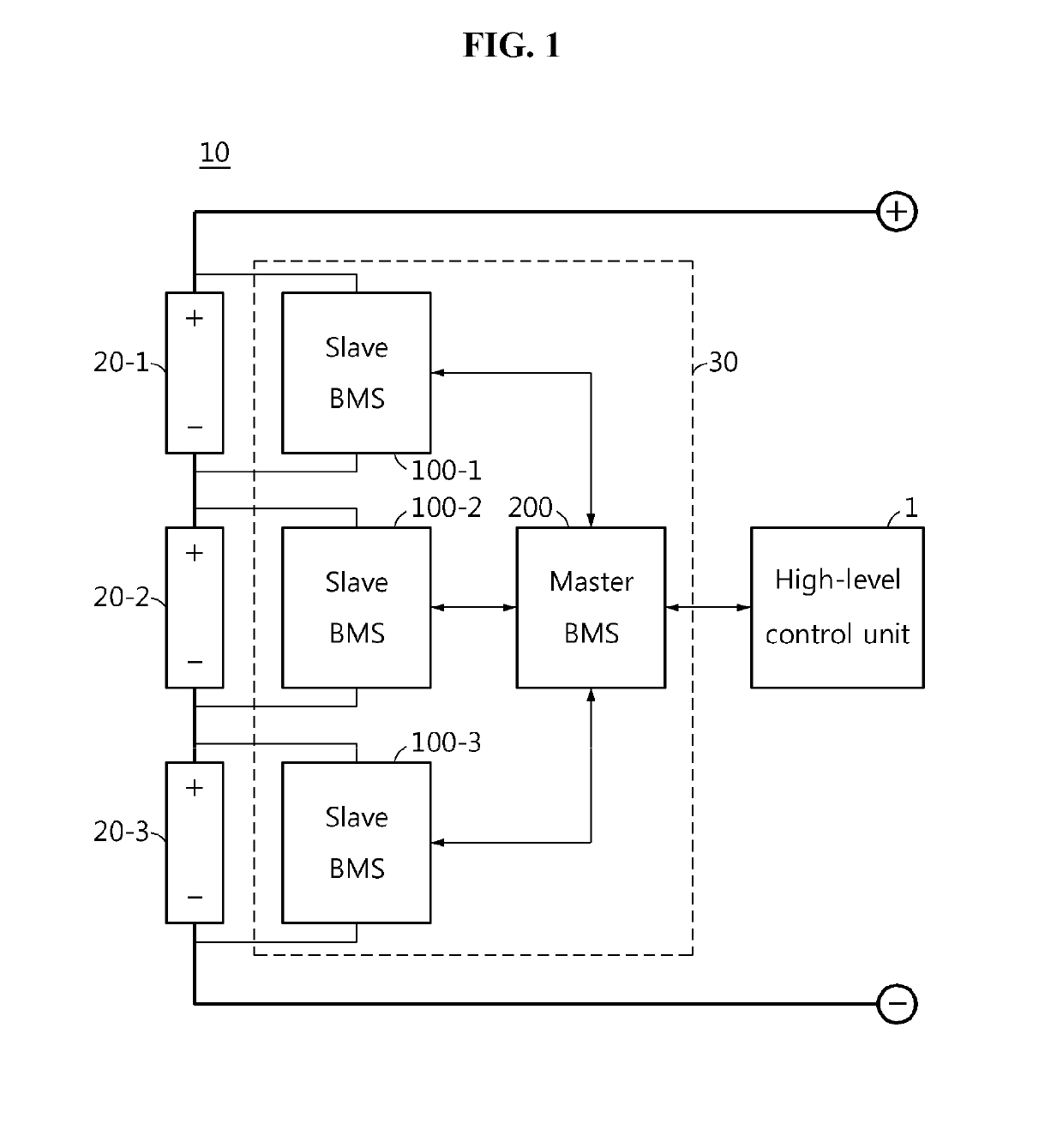
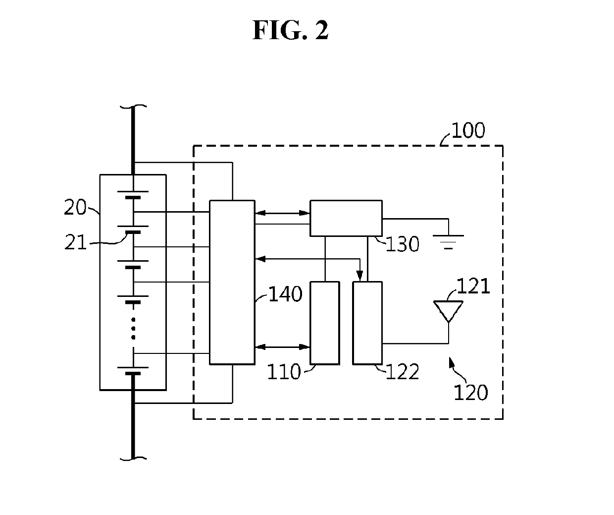
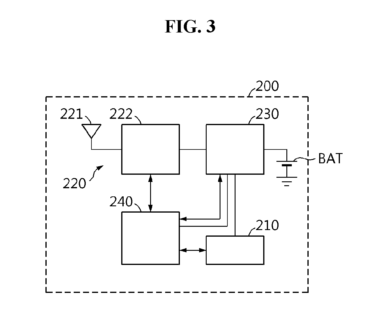
The present invention allows for baluring battery modules without adding separate circuitry through a system where each slave BMS in sleep mode can scan for a wakeup command using the electrical energy of each battery module in which it is connected. Each slave BMS adjusts the parameters related to wakeup command scanning based on the residual capacity of the battery module in which it is connected to contribute to rapid balancing and prevent overdischarge of the battery modules. Additionally, the master BMS reduces the wakeup command transmission cycle to induce any slave BMS that has not yet succeeded in scanning the wakeup command to go into active mode quickly.

Problems solved by technology

Meanwhile, due to the environment in which the battery pack operates or the electrical and chemical properties of the individual battery modules, a residual capacity deviation often occurs between the plurality of battery modules.
However, the conventional technologies including Patent Literature 1 have a limitation in the use of electrical energy of batteries because the electrical energy is not usefully utilized and just consumed away by balancing.

Method used


Image

  • Wireless battery management system and battery pack including same
  • Wireless battery management system and battery pack including same
  • Wireless battery management system and battery pack including same

Examples


Embodiment Construction

[0037]Hereinafter, the preferred embodiments of the present disclosure will be described in detail with reference to the accompanying drawings. Prior to the description, it should be understood that the terms or words used in the specification and the appended claims should not be construed as being limited to general and dictionary meanings, but interpreted based on the meanings and concepts corresponding to the technical aspects of the present disclosure on the basis of the principle that the inventor is allowed to define the terms appropriately for the best explanation.

[0038]Therefore, the embodiments described herein and illustrations shown in the drawings are just a most preferred embodiment of the present disclosure, but not intended to fully describe the technical aspects of the present disclosure, so it should be understood that a variety of other equivalents and modifications could be made thereto at the time of filing the application.

[0039]Additionally, in describing the p...


PUM

PropertyMeasurementUnit
state of chargeaaaaaaaaaa
poweraaaaaaaaaa
delay timeaaaaaaaaaa

Abstract

A wireless battery management system includes a plurality of slave BMSs coupled to a plurality of battery modules in one-to-one correspondence. Each slave BMS is configured to operate in active mode and sleep mode. Each slave BMS is configured to wirelessly transmit a detection signal indicating a state of the battery module. The wireless battery management system further includes a master BMS configured to wirelessly receive the detection signal from each of the plurality of slave BMSs. The master BMS is configured to set a scan cycle and a scan duration for each of the plurality of slave BMSs based on the detection signal, and wirelessly transmit a control signal to the plurality of slave BMSs. The control signal includes a wireless balancing command indicating the scan cycle and the scan duration set for each of the plurality of slave BMSs.

Description

TECHNICAL FIELD[0001]The present disclosure relates to a wireless battery management system, and more particularly, to a wireless battery management system for reducing a residual capacity deviation between battery modules and a battery pack including the same.[0002]The present application claims priority to Korean Patent Application No. 10-2017-0091674 filed in the Republic of Korea on Jul. 19, 2017, the disclosures of which are incorporated herein by reference.BACKGROUND ART[0003]Recently, there is dramatically growing demand for portable electronic products such as laptop computers, video cameras and mobile phones, and with the extensive development of electric vehicles, accumulators for energy storage, robots and satellites, many studies are being made on high performance secondary batteries that can be recharged repeatedly.[0004]Currently, commercially available secondary batteries include nickel-cadmium batteries, nickel-hydrogen batteries, nickel-zinc batteries, lithium secon...

Claims


Application Information

Patent Timeline
Patent Type & Authority Applications(United States)
IPC IPC(8): H01M10/42H02J7/00
CPCH01M10/425H02J7/0022H02J7/0021H01M2010/4271B60L50/50H01M10/482H01M10/4207H04W84/00B60L58/22B60L58/12B60L2260/54H02J2310/48H02J2310/18H02J7/0016H02J7/00032H02J7/0048Y02D30/70H02J7/005H02J7/0014H02J7/00
Inventor KIM, JI-EUNSUNG, CHANG-HYUNLEE, SANG-HOONCHOI, YEAN-SIK
Owner LG ENERGY SOLUTION LTD
Learn More