Three phase inverter dc-link voltage control method for reactive power overload transient process

Active Publication Date: 2019-08-01
S&C ELECTRIC
View PDF1 Cites 6 Cited by
  • Summary
  • Abstract
  • Description
  • Claims
  • Application Information

AI Technical Summary

Benefits of technology

[0007]The present disclosure describes a system and method for controlling a grid-connected reactive power compensation inverter. The system uses a combination of feedforward and feedback controls to compute a reference voltage signal based on sensor-measured voltages and currents, where the reference voltage signal is used to control the inverter switches. The disclosed method modifi

Problems solved by technology

However, during such a transient event, voltage levels within the inverter—particularly the DC-link voltage—may increase to a level where damage could be done to inverter components such as the high-power switches.
If the

Method used


Image

  • Three phase inverter dc-link voltage control method for reactive power overload transient process
  • Three phase inverter dc-link voltage control method for reactive power overload transient process
  • Three phase inverter dc-link voltage control method for reactive power overload transient process

Examples


Embodiment Construction

[0015]The following discussion of the embodiments of the disclosure directed to a three phase inverter DC-link voltage control method for reactive power transient overload is merely exemplary in nature, and is in no way intended to limit the disclosure or its applications or uses.

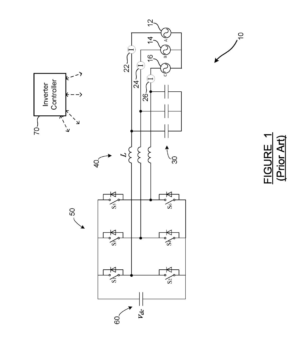
[0016]FIG. 1 is a schematic diagram of a grid-connected reactive power compensation inverter 10 of a type known in the art. The inverter 10 is not a power generator or powerplant, and does not provide real power to the grid. Rather, the inverter 10 is designed to use a capacitor bank and an array of high-speed, high-power switches to transform grid power into reactive power to compensate for local conditions on the grid—that is, to compensate for situations where grid current leads or lags grid voltage by a significant phase angle. As is known in the art, it is desirable to maintain the lead / lag phase angle of grid voltage / current within a certain band, and this is what the reactive power compensation inver...


PUM


Abstract

A system and method for controlling a grid-connected reactive power compensation inverter. The system uses a combination of feedforward and feedback controls to compute a reference voltage signal based on sensor-measured voltages and currents, where the reference voltage signal is used to control the inverter switches. The disclosed method modifies a cross-couple feedforward signal used in the reference voltage calculations, where the modified cross-couple signal includes a combination of both reference and actual currents, and the modified control scheme reduces the DC-link voltage overshoot experienced during a capacitive overload event while still providing the required reactive power and maintaining grid system stability.

Description

CROSS-REFERENCE TO RELATED APPLICATION[0001]This application claims the benefit of priority from the U.S. Provisional Application No. 62 / 622,978, filed on Jan. 28, 2018, the disclosure of which is hereby expressly incorporated herein by reference for all purposes.BACKGROUNDField[0002]The present disclosure relates generally to a control scheme for a grid-connected three phase inverter which reduces DC-link voltage overshoot. More particularly, it relates to a control method and system for a grid-connected reactive power compensation inverter which modifies a cross-couple feedforward signal used in voltage command calculations. The modified cross-couple signal includes a combination of both reference and actual currents. The modified control scheme reduces the DC-link voltage overshoot experienced during a capacitive overload event while still providing the required reactive power and maintaining system stability.Discussion of the Related Art[0003]An electrical power transmission / dis...

Claims


Application Information

Patent Timeline
IPC IPC(8): H02J3/18H02M1/34H02M7/5395H02M1/42
CPCH02J3/1828H02M1/42H02M7/537H02M1/34H02M7/5395H02M7/5387H02J3/1842Y02E40/20Y02E40/30H02M1/0003
Inventor WANG, ZITAOMCNEIL, CHRISTINEFISHER, JAMES
Owner S&C ELECTRIC
Why Eureka
Try Eureka