

Acoustic resonance spectrometry system and method
a spectrometry and acoustic resonance technology, applied in the field of brillouin scattering measurement system and non-destructive analysis of samples, can solve the problems of indentation, destructive nature, complex quantitative analysis of indents, etc., and achieve the effect of increasing sensitivity
Active Publication Date: 2019-08-08
UNIV DE BORDEAUX +5
View PDF0 Cites 2 Cited by
- Summary
- Abstract
- Description
- Claims
- Application Information
AI Technical Summary
Benefits of technology
The patent relates to a method for detecting and amplifying signals using a periodic grating of phonons. The signals are created by scattering phonons on the grating, and the method allows for the creation of high-quality images in real-time using a full-field optical imaging system. Additionally, the patent describes a way to measure the resonant Brillouin scattering of the signals at certain frequencies. This method can provide valuable information about the sample being examined.
Problems solved by technology
Indentation is, by nature, destructive.
The quantitative analysis of the indent is hence complex.
Finally, indentation does not allow quantifying the adhesion of a material.
However, the very low level of the Brillouin scattering signal generally requires a significant interaction volume.
However, the very low amplitude of the incoherent thermal phonons requires, on the one hand, degrading the spatial resolution of the images and needs, on the other hand, a point-by-point acquisition, which makes impossible the real-time image acquisition.
This technique is incompatible with the full-field imaging and does not allow deducing therefrom measurements of adhesion between materials.
The reflected beam and the back-scattered beam interfere with each other and create temporal modulations or oscillations.
Now, to our knowledge, there exists no imaging system based, for example, on a CCD camera, having a synchronous detection on each pixel of the camera, so that full-field detection on a CCD camera is not possible in picosecond acoustics.
However, the acquisition times are long, not easily compatible with imagery.
However, the intensity of the Brillouin scattering spectra is generally very low.
The drawback of this system is that the acquisition, made point-by-point, is long.
Method used
View moreImage
Smart ImageViewing Examples

Examples
first embodiment
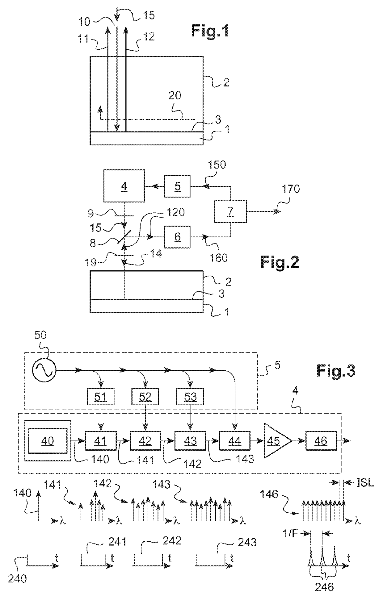
[0056]FIG. 2 schematically shows an acoustic resonance spectrometry system according to the invention;
[0057]FIG. 3 schematically illustrates the structure and operation of a pulse source of the optical comb type;
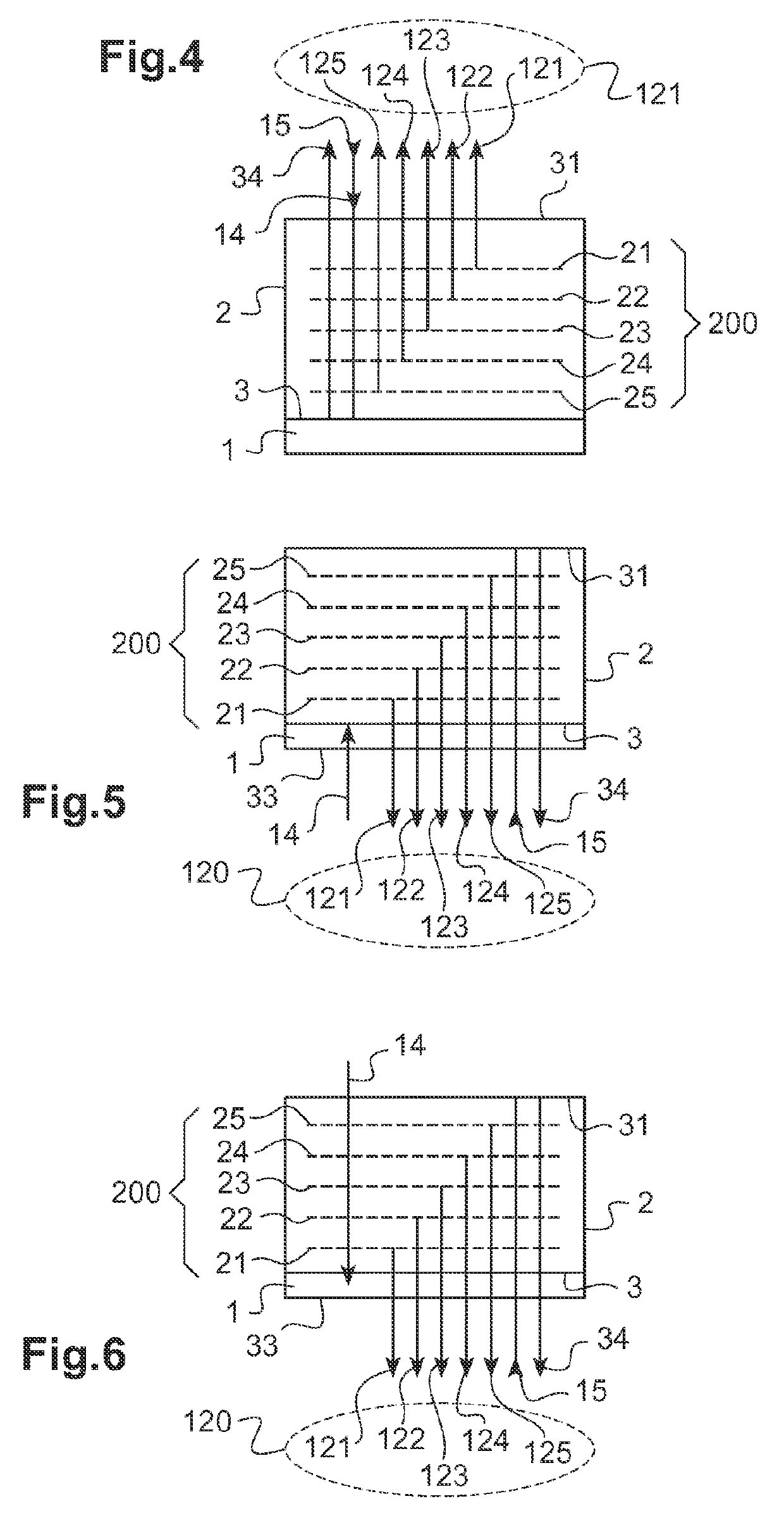
[0058]FIG. 4 illustrates a configuration for the resonant Brillouin scattering measurement according to a first embodiment of the invention;
second embodiment
[0059]FIG. 5 illustrates a configuration for the resonant Brillouin scattering measurement according to the invention;
third embodiment
[0060]FIG. 6 illustrates a configuration for the resonant Brillouin scattering measurement according to the invention;
Login to View More PUM
| Property | Measurement | Unit |
|---|---|---|
| thicknesses | aaaaa | aaaaa |
| repetition frequency | aaaaa | aaaaa |
| repetition frequency | aaaaa | aaaaa |
Abstract
Disclosed is an acoustic resonance spectrometry system for analysing a sample, which includes an optical pump-probe device adapted to generate a pump beam and a probe beam, the pump beam being consisted of a series of ultra-short pump light pulses having a repetition frequency in the spectral domain of the gigahertz, the pump beam being directed towards an optoacoustic transducer to generate a periodic grating of coherent acoustic phonons in the sample, the probe beam being directed towards the sample to form a scattering beam of the probe beam on the grating of phonons, a frequency variation device being adapted to vary the repetition frequency of the pump beam in a spectral range and a photo-detection system configured to measure a scattering signal as a function of the repetition frequency in the spectral range.
Description
TECHNICAL FIELD TO WHICH THE INVENTION RELATES[0001]The present invention generally relates to the field of devices for measuring mechanical properties of a sample at the microscopic or nanoscopic scale.[0002]More particularly, it relates to a Brillouin scattering measurement system and method for the non-destructive analysis of a sample. More precisely, it relates to a measurement of the optoacoustic type induced and detected by a light beam.TECHNOLOGICAL BACKGROUND[0003]Different techniques exist for measuring mechanical properties of elasticity of thin-film materials.[0004]Thin-film elasticity measurements are commonly performed by indentation. Indentation consists in applying a determined load at the surface of a material then measuring the indent induced by the deformation of the material. Indentation is, by nature, destructive. Moreover, indentation involves simultaneously the elastic properties of compression and shearing, as well as the plasticity of the material. The quanti...
Claims
Login to View More Application Information
Patent Timeline
 Patent Type & AuthorityApplications(United States)
IPC IPC(8): G01N21/63G01J3/44
CPCG01N21/636G01J3/4412G01N2021/638G01J2009/006H01S3/0014G01J3/2823
InventorAUDOIN, BERTRANDCORMIER, ERICLHERMITE, JEROMESANTARELLI, GIORGIOGUILLET, YANNICKAUBOURG, ADRIEN
OwnerUNIV DE BORDEAUX