Transmitting device, receiving device, quantum key distribution method, and quantum key distribution program for quantum key distribution system

Active Publication Date: 2019-08-08
NEC CORP +2
View PDF0 Cites 2 Cited by
  • Summary
  • Abstract
  • Description
  • Claims
  • Application Information

AI Technical Summary

Benefits of technology

[0024]According to this invention, it is possible to suppress degradation o

Problems solved by technology

At the present stage, however, the single-photon light source is on the road to development and does not reach a practical level.
However, taking t

Method used


Image

  • Transmitting device, receiving device, quantum key distribution method, and quantum key distribution program for quantum key distribution system
  • Transmitting device, receiving device, quantum key distribution method, and quantum key distribution program for quantum key distribution system
  • Transmitting device, receiving device, quantum key distribution method, and quantum key distribution program for quantum key distribution system

Examples


Example

Example Embodiment

[0044]Now, an example embodiment of the present invention will be described in detail with reference to the drawings. Herein, description will be simplified or omitted as appropriate about configurations and operations having a weak relationship to the present invention.

[0045]FIG. 5 is a block diagram for illustrating a configuration of the quantum key distribution system according to an example embodiment of the present invention. As shown in FIG. 5, the quantum key distribution system 100 comprises a transmitting device 110 and a receiving device 120. Each of unidirectional arrows in FIG. 5 simply depicts a direction of flow of a signal (data) without excluding bidirectionality.

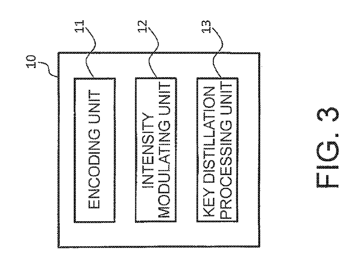
[0046]At first, the transmitting device 110 will be described. The transmitting device 110 comprises an optical source unit 111, an encoding unit 112, a decoy modulating unit 113, an optical attenuating unit 114, and a first key distillation processing unit 115.

[0047]The optical source uni...


PUM


Abstract

A quantum key distribution device is provided with an encoding unit which encodes an optical pulse train; an intensity modulating unit which subjects the encoded optical pulse train to N (where N is an integer at least equal to 3) types of intensity modulation having mutually different intensities, with different timings; and a first key distillation processing unit which generates an encryption key on the basis of a data sequence obtained by removing data obtained from an optical pulse having a specific modulation pattern from a data sequence used by the encoding unit and the intensity modulating unit.

Description

TECHNICAL FIELD[0001]This invention relates to a transmitting device, a receiving device, a quantum key distribution method, and a quantum key distribution program for a quantum key distribution system.BACKGROUND ART[0002]In recent years, as a method for achieving encrypted communication having absolute safety against an eavesdropping action, quantum key distribution (Quantum Key Distribution, QKD) (Non-Patent Document 1) has been actively studied and developed for practical use.[0003]Non-Patent Document 1 proposes to use a single-photon light source as a light source for the QKD. At the present stage, however, the single-photon light source is on the road to development and does not reach a practical level. Therefore, as a substitute for the single-photon light source, the mainstream is a method of using, as a pseudo-single-photon light source, a laser light source having a weakened intensity obtained by extremely weakening an intensity of a general laser light source.[0004]However...

Claims


Application Information

Patent Timeline
IPC IPC(8): H04L9/08H04B10/508H04J7/00H04L29/06
CPCH04L9/0858H04B10/508H04J7/00H04L63/1475H04B10/516H04B10/70H04L9/08H04L9/12
Inventor YOSHINO, KEN-ICHIROFUJIWARA, MIKIOSASAKI, MASAHIDETOMITA, AKIHISA
Owner NEC CORP
Why Eureka
Try Eureka