
Composite cable and wire harness

a technology of composite cables and wire harnesses, which is applied in the direction of power cables, cables, insulated conductors, etc., can solve the problems of complex manufacturing process of composite cables, and achieve the effect of maintaining the bending resistance of composite cables and being easy to manufactur

Active Publication Date: 2019-08-15
HITACHI METALS LTD
View PDF7 Cites 8 Cited by
  • Summary
  • Abstract
  • Description
  • Claims
  • Application Information

AI Technical Summary

Benefits of technology

The present invention provides a composite cable and wire harness that are easy to manufacture while maintaining their bending resistance. This is achieved by using a simple manufacturing process that does not significantly increase the cost of the cable.

Problems solved by technology

To improve the bending resistance, however, it is not preferable from the viewpoint of manufacturing cost that the manufacturing process of the composite cable becomes complicated.

Method used


Image

  • Composite cable and wire harness
  • Composite cable and wire harness
  • Composite cable and wire harness

Examples


embodiment

[0017]An embodiment of the present invention will be described below with reference to the accompanying drawings.

[0018](Explanation of a Vehicle to which a Composite Cable is Applied)

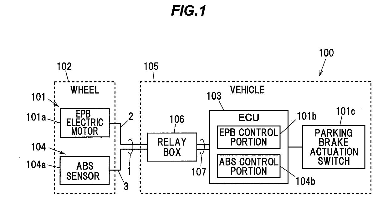
[0019]FIG. 1 is a block diagram showing a configuration of a vehicle using a composite cable according to the present embodiment.

[0020]As shown in FIG. 1, the vehicle 100 is provided with an electric parking brake (hereinafter referred to as “EPB”) 101 as an electrically driven braking device.

[0021]The EPB 101 includes an EPB electric motor 101a and an EPB control portion 101b.

[0022]The EPB electric motor 101a is mounted in a wheel 102 of the vehicle 100. The EPB control portion 101b is mounted in an ECU (electronic control unit) 103 of the vehicle 100. Note that the EPB control portion 101b may be mounted in a control unit other than the ECU 103 or may be mounted in a dedicated hardware unit.

[0023]The EPB electric motor 101a is provided with a piston (not shown) to which a brake pad is attached, so th...


PUM


Abstract

A composite cable is composed of a twisted pair formed by twisting together one pair of first electric wires each including a first conductor and a first insulation covering an outer circumference of the first conductor, one pair of second electric wires each including a second conductor greater in cross sectional area than the first conductor and a second insulation covering an outer circumference of that second conductor, the second electric wire being greater in outer diameter than the first electric wire, and a sheath covering aggregates together formed by stranding together the twisted pair and the one pair of second electric wires. The first conductors are formed by stranding a plurality of metal wires together. The second conductors are formed by stranding a plurality of aggregated strands together formed by stranding a plurality of metal wires together.

Description

CROSS-REFERENCE TO RELATED APPLICATION[0001]The present application is based on Japanese patent application No. 2018-023586 filed on Feb. 13, 2018, the entire contents of which are incorporated herein by reference.BACKGROUND OF THE INVENTION OF THE INVENTION1. Field of the Invention[0002]The present invention relates to a composite cable and a wire harness, and more particularly to a composite cable and a wire harness for connecting a wheel side and a vehicle body side together in a vehicle such as an automobile.2. Description of the Related Art[0003]In recent years, electrically driven braking devices have been used in vehicles such as automobiles. As the electrically driven braking devices, an electro-mechanical brake (EMB) and an electric parking brake (EPB) are known.[0004]The electromechanical brake is also simply referred to as an electrically driven brake or an electric brake, and is configured to control the rotational driving force of dedicated electric motors provided in e...

Claims


Application Information

Patent Timeline
IPC IPC(8): B60R16/02B60R16/03H01B7/02H01B9/00
CPCB60R16/0215B60R16/03H01B7/0216H01B9/006H01B7/0009H01B7/041H01B13/02H01B9/003H01B7/1885
Inventor HAYAKAWA, YOSHIKAZUMURAYAMA, TOMOYUKIITO, HIROYUKIESHIMA, HIROTAKAFUTATSUMORI, TAKAHIRO
Owner HITACHI METALS LTD
Features
  • Generate Ideas
  • Intellectual Property
  • Life Sciences
  • Materials
  • Tech Scout
  • Unparalleled Data Quality
  • Higher Quality Content
  • 60% Fewer Hallucinations
Learn More