

Outlet guide vane for turbomachine, made from several parts assembled together by attachment means outside the flow stream
- Summary
- Abstract
- Description
- Claims
- Application Information
AI Technical Summary
Benefits of technology
Problems solved by technology
Method used
Image

Examples
Embodiment Construction
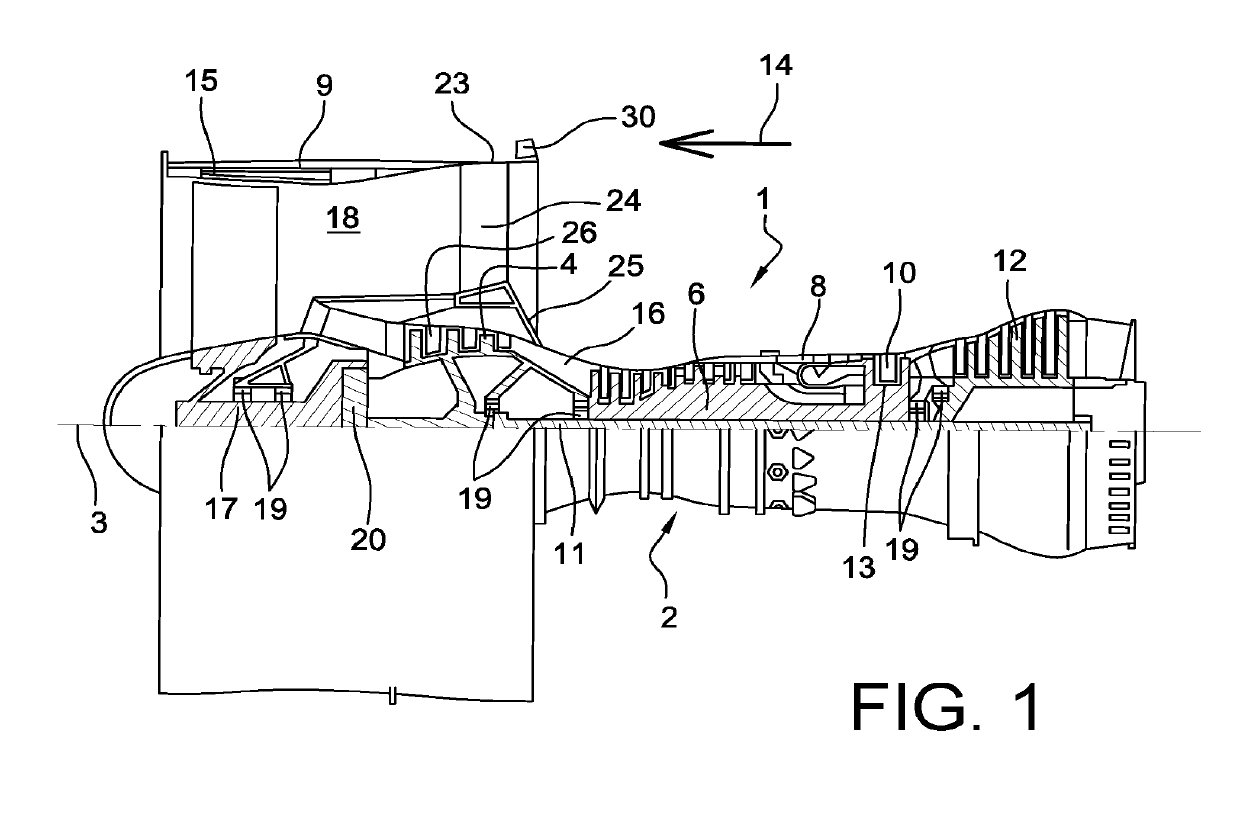
[0045]With reference to FIG. 1, the figure represents a twin-spool twin-flow turbojet, with a high dilution ratio. The turbojet 1 conventionally comprises a gas generator 2 with a low pressure compressor 4 on one side and a low pressure turbine 12 on the other side, this gas generator 2 comprising a high pressure compressor 6, a combustion chamber 8 and a high pressure turbine 10. In the following, the terms “forward” and aft” are considered along a direction 14 opposite to the main flow direction of gases in the turbojet, this direction 14 being parallel to the longitudinal axis 3 of the turbojet. On the other hand, the terms “upstream” and “downstream” are considered along the main flow direction of gases within the turbojet.
[0046]The low pressure compressor 4 and the low pressure turbine 12 form a low pressure case, and are connected to each other through a low pressure shaft 11 centred on the axis 3. Similarly, the high pressure compressor 6 and the high pressure turbine 10 form...
PUM
| Property | Measurement | Unit |
|---|---|---|
| Time | aaaaa | aaaaa |
| Thermal conductivity | aaaaa | aaaaa |
| Aerodynamic | aaaaa | aaaaa |
Abstract
Description
Claims
Application Information