
Efficient mems-based eye tracking system with a silicon photomultiplier sensor

Active Publication Date: 2019-08-15
MICROSOFT TECH LICENSING LLC
View PDF11 Cites 4 Cited by
  • Summary
  • Abstract
  • Description
  • Claims
  • Application Information

AI Technical Summary

Benefits of technology

The patent text describes a new invention that has certain characteristics and advantages. The technical effects of this invention will be explained in detail in the following description and quickly summarized for easy understanding.

Problems solved by technology

However, these new eye tracking technologies are available, they are seriously lacking.
In particular, the current technology is quite costly because it often requires additional hardware (e.g., specialized cameras) on the HMD to capture the user's eye movements.
Additionally, these cameras are placed in close proximity to the eyes and typically obstruct the user's field of view.
Furthermore, the current technology is deficient because it consumes a large amount of battery resources.

Method used


Image

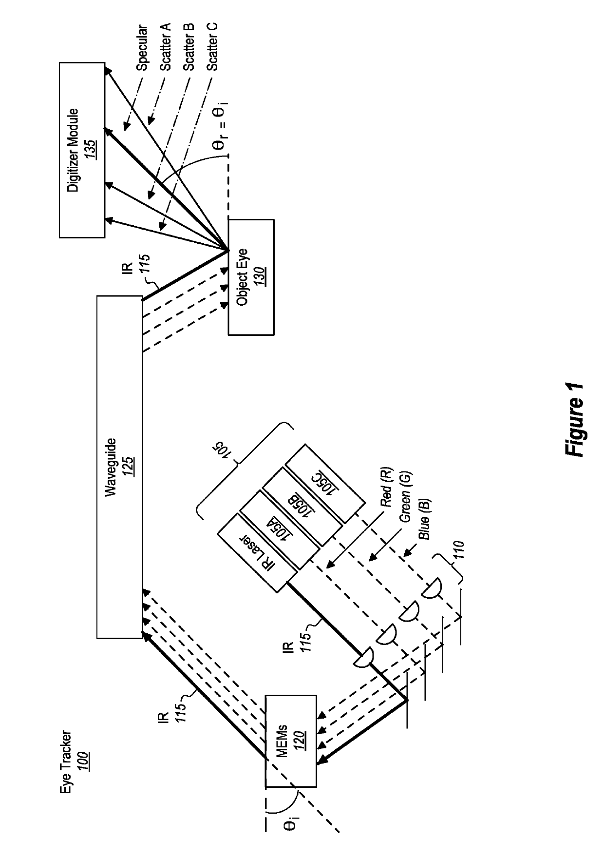
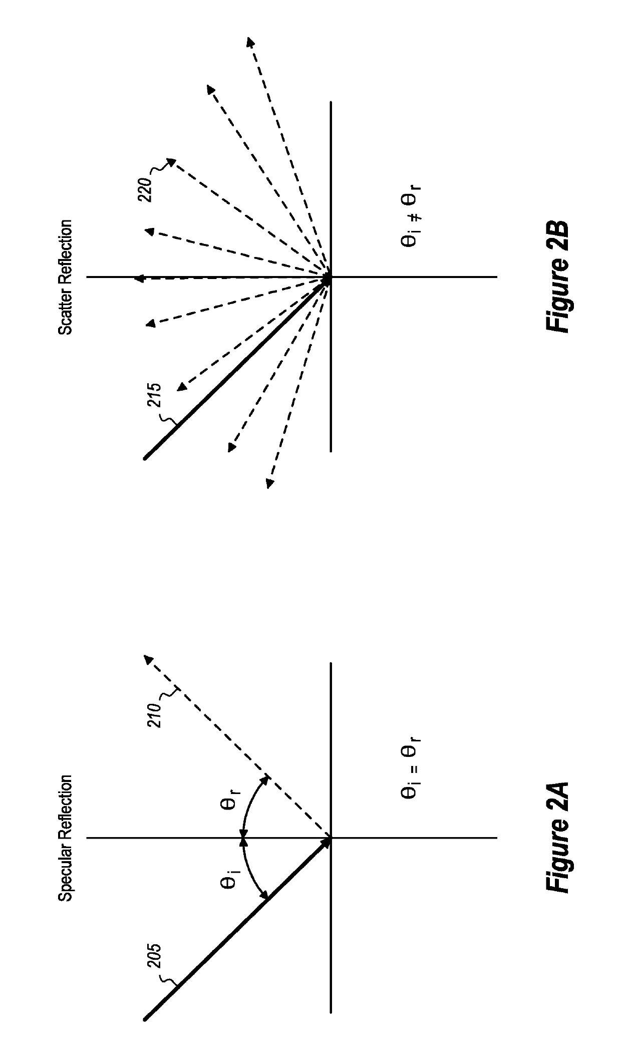
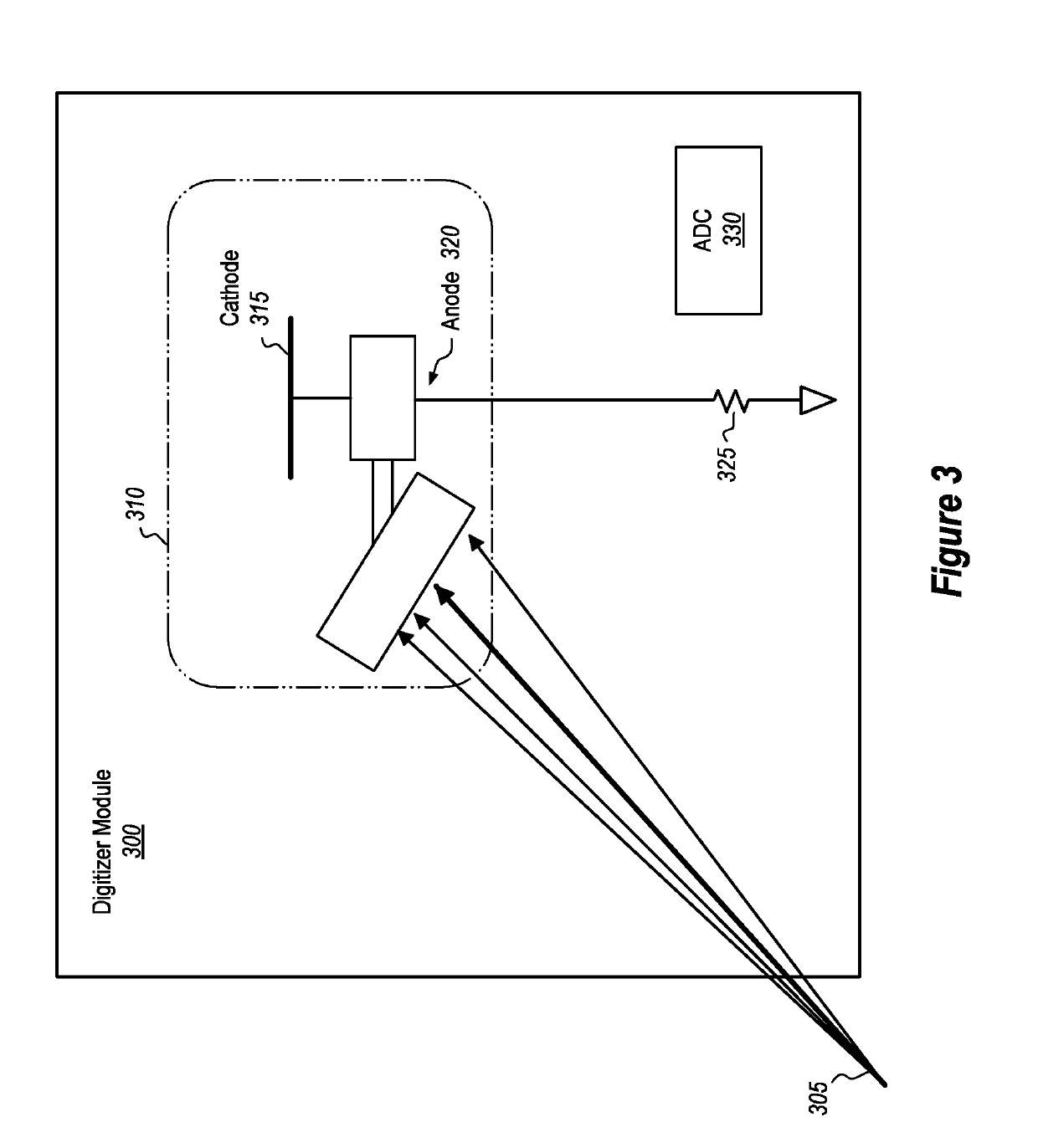
  • Efficient mems-based eye tracking system with a silicon photomultiplier sensor
  • Efficient mems-based eye tracking system with a silicon photomultiplier sensor
  • Efficient mems-based eye tracking system with a silicon photomultiplier sensor

Examples


example method (

Example Method(s)

[0135]The following discussion now refers to a number of methods and method acts that may be performed. Although the method acts may be discussed in a certain order or illustrated in a flow chart as occurring in a particular order, no particular ordering is required unless specifically stated, or required because an act is dependent on another act being completed prior to the act being performed. These methods are implemented by one or more processors of a computer system (e.g., the computer system 1200 of FIG. 12). By way of example, a computer system includes one or more computer-readable hardware storage media that store computer-executable code. This computer-executable code is executable by the one or more processors to cause the computer system to perform these methods

[0136]FIG. 13 illustrates an example method 1300 for generating an image of an eye of a user. Of note, method 1300 may be performed by the computer system 1200 shown in FIG. 12.

[0137]As shown, su...


PUM


Abstract

Eye tracking system incorporates and / or uses one or more silicon photomultiplier (SiPM) sensor and an infrared module of a microelectromechanical (MEMs)-based scanner. The infrared module emits a beam of photons, where at least some of the photons are directed towards a user's eye while the eye tracking system is being used. The SiPM sensor(s) capture a reflection that emanates off of the user's eye.

Description

RELATED APPLICATIONS[0001]This application is related to co-pending U.S. patent application Ser. No. ______, filed on Feb. 9, 2018, entitled “EYE TRACKING SYSTEM FOR USE IN A VISIBLE LIGHT DISPLAY DEVICE,” and which application is expressly incorporated herein by reference in its entirety.BACKGROUND[0002]Mixed-reality systems, including virtual-reality and augmented-reality systems, have recently received significant interest for their ability to create immersive experiences for users. Conventional augmented-reality (AR) systems create an augmented reality scenario by generating holograms that are rendered in the user's line of sight to objects in the real world. In contrast, conventional virtual-reality (VR) systems create a more immersive experience because a user's entire view is obstructed by a virtual world.[0003]As used herein, AR and VR systems are described and referenced interchangeably using the umbrella term “mixed-reality system(s).” Unless specifically stated or unless ...

Claims


Application Information

Patent Timeline
IPC IPC(8): G06F3/01G09G5/391G09G3/02G01S17/66G01J1/44G01J1/04
CPCG06F3/013G09G5/391G09G3/02G01S17/66G01J1/44G01J1/0437G09G2354/00G09G2340/0407G09G2340/0464G01J2001/4453G06F3/017
Inventor PRICE, RAYMOND KIRKZANG, KAIGIBSON, GREGORY THEODORE
Owner MICROSOFT TECH LICENSING LLC
Learn More