Interactive hearing aid error detection

a technology of error detection and hearing aids, applied in the field of hearing aids and hearing aid systems, can solve the problems of compromising insufficient sound volume, patient discomfort, etc., and achieve the effect of optimizing the performance of hearing aids, and optimizing the performance of hearing aid systems

Inactive Publication Date: 2019-08-15
EARLENS CORP
View PDF0 Cites 27 Cited by
  • Summary
  • Abstract
  • Description
  • Claims
  • Application Information

AI Technical Summary

Benefits of technology

[0007]The present invention is adapted to assist in optimizing the performance of a hearing aid by detecting conditions which result in sub-optimal performance and assisting a user or health care professional to correct those conditions. In one embodiment, the present invention is adapted to optimize the performance of a hearing aid by generating a reference signal which, when broadcast, creates a feedback signal. The feedback signal may then be measured, or its characteristics identified, to determine whether the hearing aid system is optimized and, if not, what components or characteristics are not optimized and how to optimize the hearing aid system performance or that of its components.

Problems solved by technology

Since this positioning depends on user's subjective impression of the sound quality, the position chosen may not be optimal and / or may change from insertion to insertion.
Sub-optimal ear tip positioning may result in insufficient sound volume, patient discomfort, and / or increased feedback.
Hearing aid users also encounter problems with ear tip positioning because ear tips may change shape (e.g., as a result of wear or fatigue) over time, resulting in a sub-optimal fit and / or a tendency to migrate.
Users may not notice these changes and may continue to use the worn / fatigued ear tip, compromising the performance of the hearing aid.
Worn or fatigued ear tips may cause the same types of audio problems as the sub-optimal ear tip placement discussed above.
Since this method of aligning the transmitter and receiver depends on the sound quality as perceived by the user, the resulting ear tip location may not be optimal.
Sub-optimal ear tip location may cause, for example, insufficient sound volume, sub-optimal optical coupling, patient discomfort, and / or increased feedback.
For example, in a light driven hearing aid, the component which sits on the tympanic membrane may migrate from its original position over time, resulting in degraded system performance.
For example, in a contact hearing aid which utilizes a tympanic lens, the migration of the tympanic lens may result in misalignment between the tympanic lens and the tympanic membrane, degrading system performance.

Method used


Image

  • Interactive hearing aid error detection
  • Interactive hearing aid error detection
  • Interactive hearing aid error detection

Examples


Embodiment Construction

Definitions

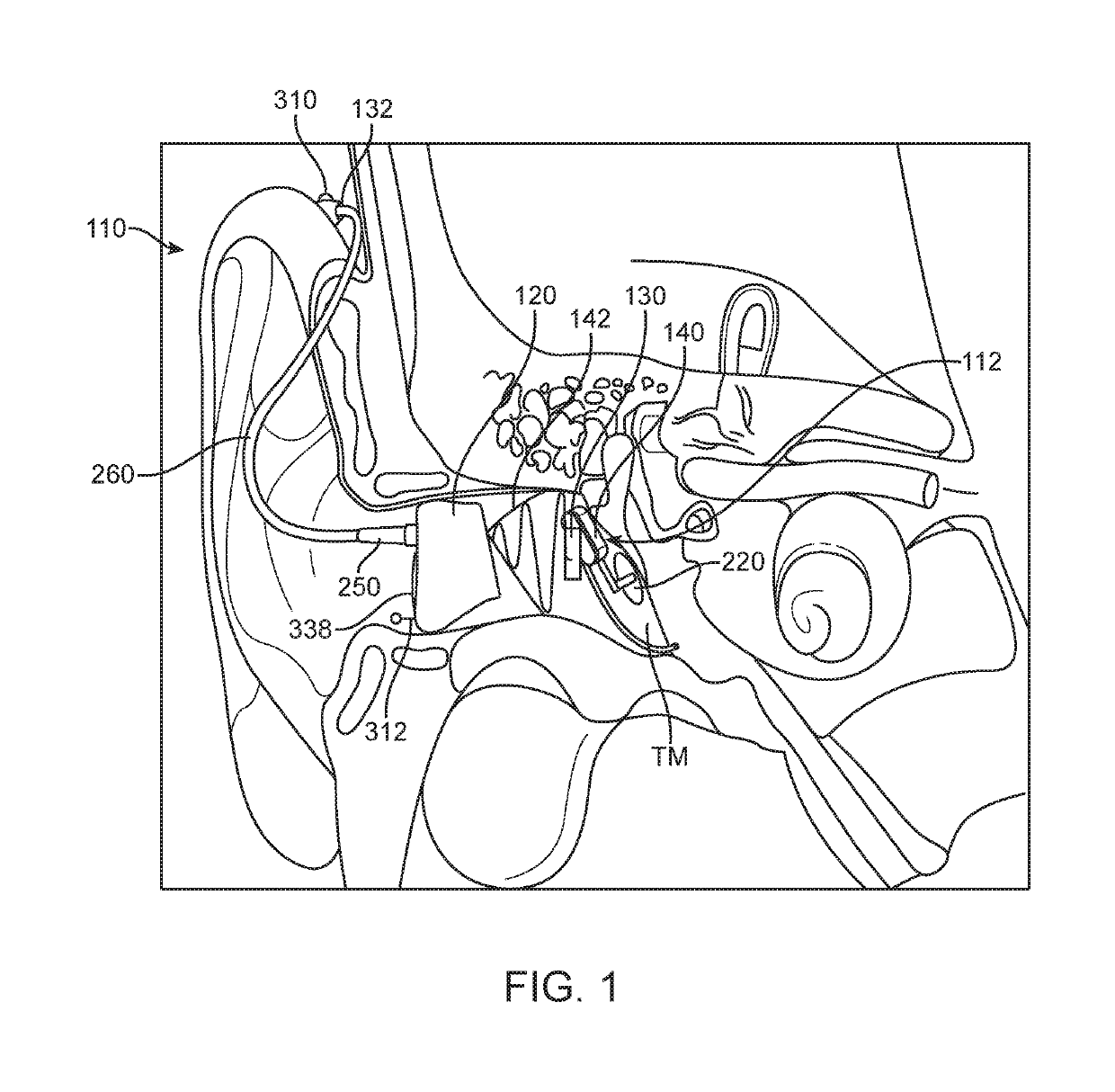
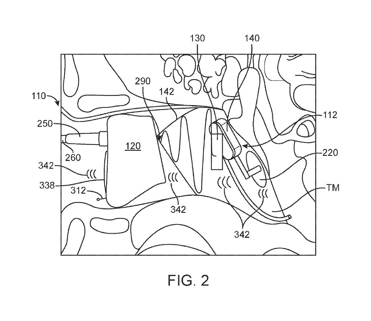
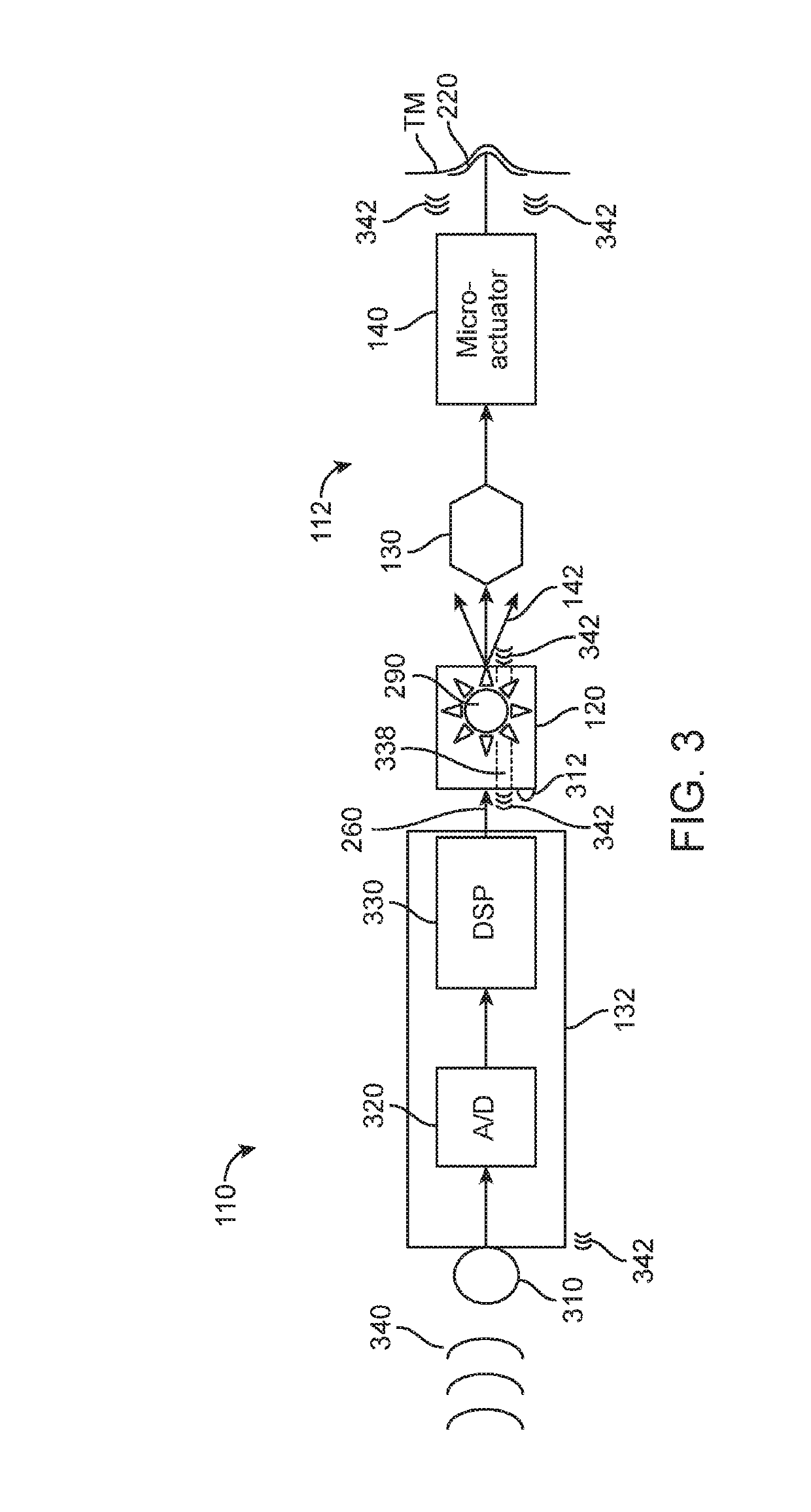
[0017]Audio Processor (BTE)—A system for receiving and processing audio signals. In embodiments of the invention, audio processors may include one or more microphones adapted to receive audio which reaches the user's ear. In embodiments of the invention, the audio processor may include one or more components for processing the received sound. In embodiments of the invention, the audio processor may include digital signal processing electronics and software which are adapted to process the received sound. In embodiments of the invention, processing of the received sound may include amplification of the received sound.

[0018]Contact Hearing System—A system including a contact hearing device, an ear tip and an audio processor. In embodiments of the invention, contact hearing systems may also include an external communication device. An example of such system is the Earlens light driven hearing-aid, available from the Earlens Corporation, which transmits audio signal by laser ...


PUM


Abstract

The present invention is adapted to assist in optimizing the performance of a hearing aid by detecting conditions which result in sub-optimal performance and assisting a user or health care professional to correct those conditions. The present invention is adapted to optimize the performance of a hearing aid by generating a reference signal which, when broadcast, creates a feedback signal. The feedback signal is then measured, or its characteristics identified, to determine whether the hearing aid system is optimized and, if not, what components or characteristics are not optimized and how to optimize the hearing aid system performance or that of its components.

Description

CROSS-REFERENCE[0001]This application is a continuation of PCT Application No. PCT / US2017 / 058086, filed Oct. 24, 2017; which claims the benefit of U.S. Provisional Application No. 62 / 414,588, filed Oct. 28, 2016; which are incorporated herein by reference in their entirety.BACKGROUND OF THE INVENTIONField of the Invention[0002]The present disclosure is related to hearing aids, hearing aid systems, and control methods therefor.Technical Background[0003]In hearing aids where the position of the in-canal, or “ear tip”, portion of the hearing aid has an impact on the overall performance of the hearing aid, hearing-aid users typically position the in-canal, or “ear tip”, portion of the hearing aid in their ear canal using subjective cues. The ear tip may be positioned by, for example, finding a “sweet spot” where the sound from the hearing aid is most intelligible. Since this positioning depends on user's subjective impression of the sound quality, the position chosen may not be optimal ...

Claims


Application Information

Patent Timeline
Patent Type & Authority Applications(United States)
IPC IPC(8): H04R25/00
CPCH04R25/30H04R25/40H04R25/604H04R25/70H04R25/02H04R25/50H04R25/606H04R29/00
Inventor UNNO, TAKAHIRORATHNAM, LAKSHMANSANDHU, KULBIRFLAHERTY, BRYANKHALEGHIMEYBODI, MORTEZA
Owner EARLENS CORP
Why Eureka
Try Eureka