Surface cleaning apparatus with a variable inlet flow area

a cleaning apparatus and variable technology, applied in the direction of motor fan assembly mounting, suction cleaner, domestic application, etc., can solve the problems of increasing the number of types of debris, reducing the power utilization rate, and limited weight and/or power output of the suction motor, so as to achieve greater airflow performance, longer run time, and greater lifting power

Active Publication Date: 2019-08-22
OMACHRON INTPROP
View PDF9 Cites 4 Cited by
  • Summary
  • Abstract
  • Description
  • Claims
  • Application Information

AI Technical Summary

Benefits of technology

[0011]In some cases, a preferred trade-off between airflow performance and lifting power may depend on the intended use of the surface cleaning apparatus. For example, when cleaning a floor surface by translating a surface cleaning head across the floor surface, it may be considered desirable to provide a relatively high lifting power, as this may allow relatively heavy and / or large debris to be transported to the air treatment member. For example, this may increase the number of types of debris that the surface cleaning apparatus can ‘pick-up’ from the floor surface. As another example, when cleaning surfaces other than floor surfaces (e.g. tabletops, furniture, shelves, wall surfaces) it may be considered desirable to provide a relatively high airflow (which may be characterized as a relatively high mass transport rate), as this may allow the surface cleaning apparatus to transport a larger quantity of dust and debris to the air treatment member per unit time.
[0012]Without intending to be bound by theory, the ‘lifting power’ of a surface cleaning apparatus may be considered generally proportional to the velocity of air flowing from the dirty air inlet to the inlet of an air treatment member. Accordingly, where a suction motor and / or fan assembly is operated at a constant rate (e.g. at a constant power level), the ‘lifting power’ may be considered proportional to the cross-sectional area of the air flow path between the dirty air inlet and the inlet of the air treatment member. Accordingly, all else being substantially equal, the ‘lifting power’ of a surface cleaning apparatus may be increased by reducing the cross-sectional area of the air flow path to the air treatment member, and the airflow throughput of the surface cleaning apparatus may be increased by increasing the cross-sectional area of the air flow path to the air treatment member (e.g. by reducing the ‘drag’ or other aerodynamic inefficiencies of a narrower air flow path).
[0013]The power utilized to produce a particular velocity of air flow will depend, inter alia, on the cross-sectional area of the air flow path. A smaller cross-sectional area (e.g., a smaller pipe diameter) will produce more back pressure. Therefore, more power will be required to produce a higher velocity. When a surface cleaning apparatus is operated in a cordless mode, the on board energy storage members have a finite amount of power. Therefore, the greater the velocity of the air flow, the lower the run time of the surface the cleaning apparatus. Conversely, by increasing the cross-sectional area, a lower velocity is achieved, but a higher air flow (CFM) may be obtained with a lower back pressure. The lower back pressure may result in a lower power utilization rate and therefore a longer run time from the on board energy storage members.
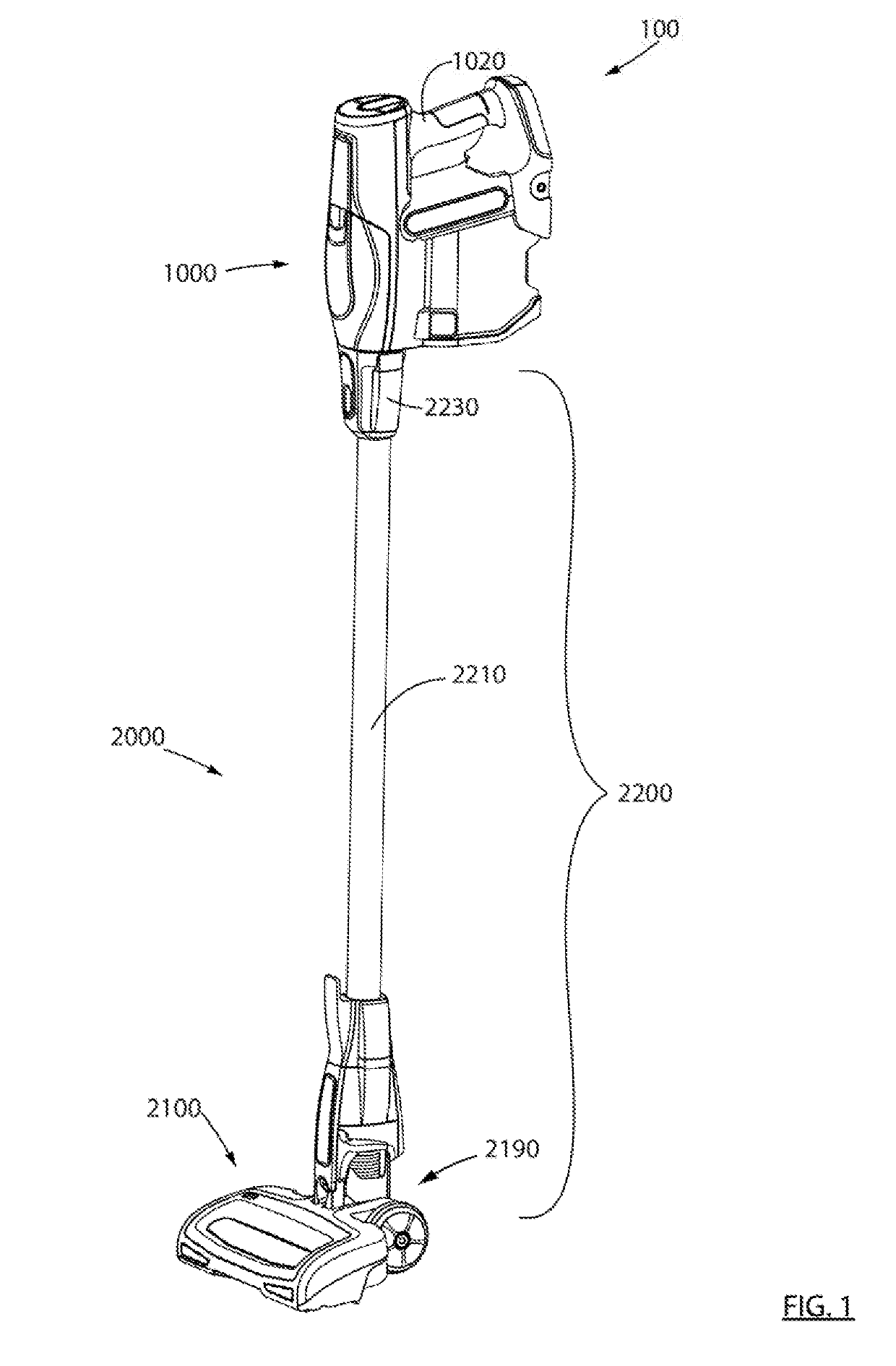
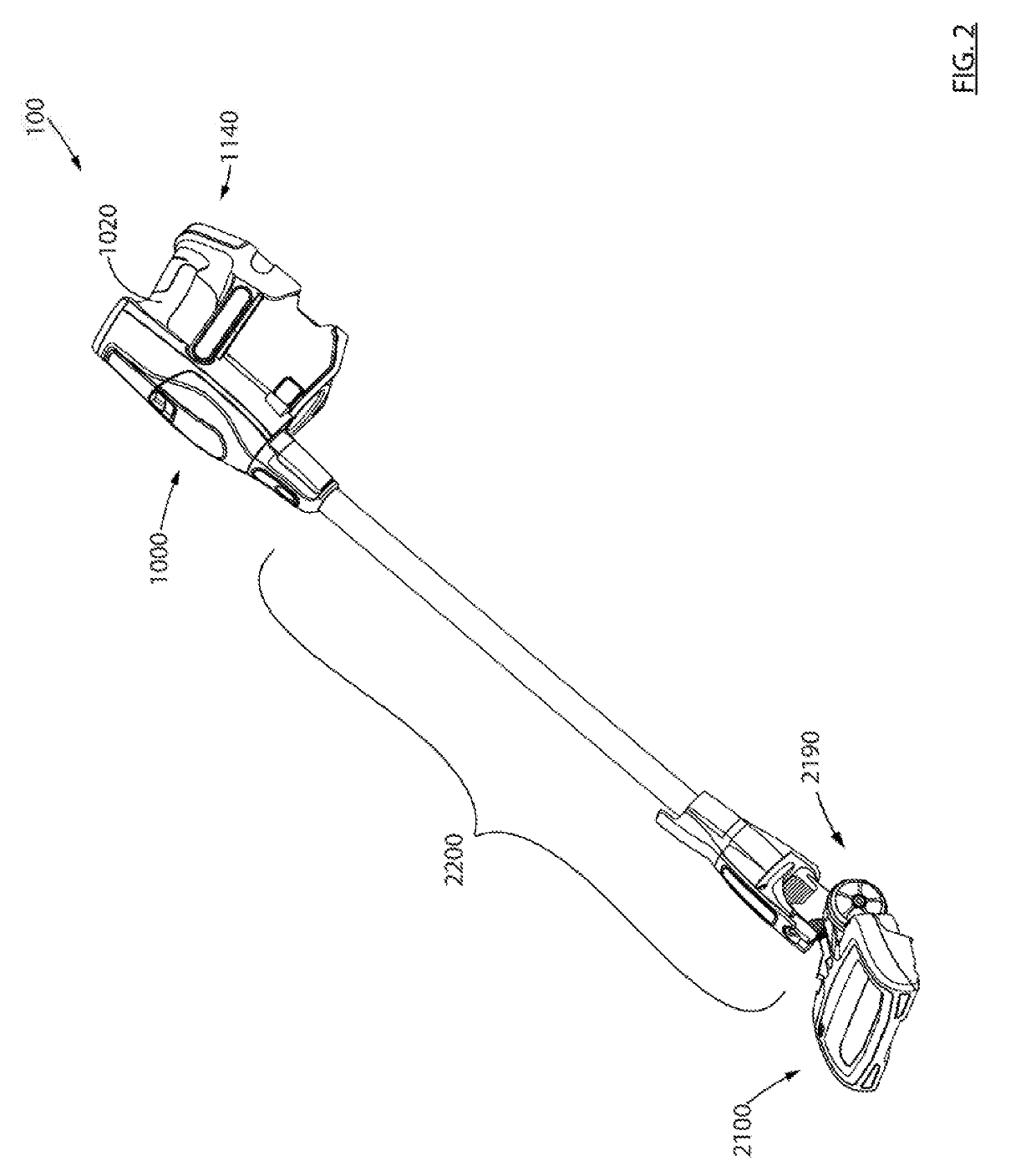
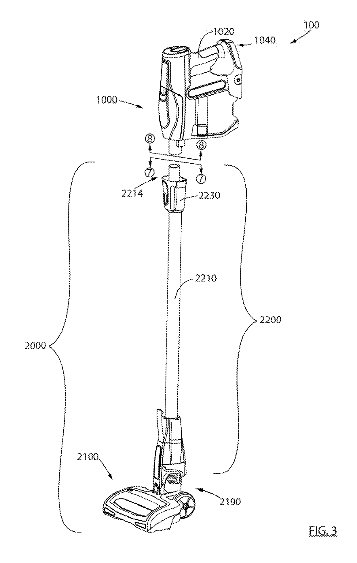
[0016]Providing a reconfigurable surface cleaning apparatus in which a velocity of air through the rigid wand (in a floor cleaning mode) is greater than a velocity of air to the air treatment member (in an above floor cleaning mode) may have one or more advantages. For example, the surface cleaning apparatus may have a greater ‘lifting power’ in the floor cleaning mode (when this performance characteristic may be considered particularly desirable), and a greater airflow performance in the above floor cleaning mode (when this performance characteristic may be considered particularly desirable). A further advantage is that by using a lower velocity or a larger cross-sectional flow are in the above floor cleaning mode, a longer run time may be obtained on a single change of the on board energy storage members.
[0048]An advantage of this design is that the reconfigurable surface cleaning apparatus may have a greater ‘lifting power’ in the floor cleaning mode, and a greater airflow performance in the above floor cleaning mode.
[0076]Providing the cyclone air inlet no more than, e.g., 20 inches above the floor may have one or more advantages. For example, this height to which dirt and debris must be lifted to enter, e.g., a cyclone chamber, is reduced. Accordingly, the power needed to lift the dirt and debris for treatment in the air treatment member may be reduced. It will be appreciated that it need not be necessary for the heavier or denser dirt and debris to exit the cyclone chamber and enter a dirt collection chamber. The heavier or denser dirt and debris may remain in the cyclone chamber. In such a case, the cyclone chamber is preferably openable, optionally concurrently with the dirt collection chamber.

Problems solved by technology

However, where the suction motor of a hand vacuum cleaner is powered by an onboard energy storage member (e.g. one or more rechargeable batteries), the weight and / or power output of the suction motor may be limited, e.g. due to the weight, cost, and / or other concerns of, e.g., the on board energy storage members (e.g., a battery pack).
For example, this may increase the number of types of debris that the surface cleaning apparatus can ‘pick-up’ from the floor surface.
The lower back pressure may result in a lower power utilization rate and therefore a longer run time from the on board energy storage members.

Method used


Image

  • Surface cleaning apparatus with a variable inlet flow area
  • Surface cleaning apparatus with a variable inlet flow area
  • Surface cleaning apparatus with a variable inlet flow area

Examples


Embodiment Construction

[0165]Various apparatuses, methods and compositions are described below to provide an example of an embodiment of each claimed invention. No embodiment described below limits any claimed invention and any claimed invention may cover apparatuses and methods that differ from those described below. The claimed inventions are not limited to apparatuses, methods and compositions having all of the features of any one apparatus, method or composition described below or to features common to multiple or all of the apparatuses, methods or compositions described below. It is possible that an apparatus, method or composition described below is not an embodiment of any claimed invention. Any invention disclosed in an apparatus, method or composition described below that is not claimed in this document may be the subject matter of another protective instrument, for example, a continuing patent application, and the applicant(s), inventor(s) and / or owner(s) do not intend to abandon, disclaim, or d...


PUM


Abstract

A reconfigurable surface cleaning apparatus includes a floor cleaning unit comprising a surface cleaning head, and a hand vacuum cleaner. The reconfigurable surface cleaning apparatus is operable in a floor cleaning mode in which the hand vacuum cleaner is mounted to a rigid wand of the floor cleaning unit and operated using an energy storage member of the hand vacuum cleaner, and also operable in an above floor cleaning mode in which the hand vacuum cleaner is disconnected from air flow with the floor cleaning unit and operated using the energy storage member. A cross-sectional area through the rigid wand is less than a cross-sectional area through an upstream portion of an airflow path of the hand vacuum cleaner. A velocity of air travelling through the wand in the floor cleaning mode is greater than a velocity of air flow through the upstream portion in the above floor cleaning mode.

Description

CROSS REFERENCE TO RELATED APPLICATIONS[0001]This application is a continuation-in-part of U.S. patent application Ser. No. 16 / 106,229 filed on Aug. 21, 2018, which is pending, which itself is a continuation of U.S. patent application Ser. No. 15 / 046,895, filed on Feb. 18, 2016, which issued as U.S. Pat. No. 10,076,217 on Sep. 18, 2018, which itself is a continuation of U.S. patent application Ser. No. 14 / 036,818, which issued as U.S. Pat. No. 9,301,662 on Apr. 5, 2016, which itself is a continuation of U.S. patent application Ser. No. 13 / 396,918 filed on Feb. 15, 2012, which issued as U.S. Pat. No. 8,567,006 on Oct. 29, 2013, which is itself a continuation of U.S. patent application Ser. No. 11 / 954,310 filed on Dec. 12, 2007, which issued as U.S. Pat. No. 8,166,607 on May 1, 2012, which claims priority from U.S. Provisional Patent Application No. 60 / 869,586, filed on Dec. 12, 2006, each of which is incorporated herein by reference in its entirety.FIELD[0002]This disclosure relates ...

Claims


Application Information

Patent Timeline
Patent Type & Authority Applications(United States)
IPC IPC(8): A47L5/22A47L5/32A47L5/36
CPCA47L5/225A47L5/32A47L5/365A47L5/28A47L9/165A47L9/1608A47L5/24A47L9/2884A47L9/325A47L9/322A47L5/36A47L9/22
Inventor CONRAD, WAYNE ERNEST
Owner OMACHRON INTPROP
Why Eureka
Try Eureka