Handpiece Apparatus, System, and Method for Laser Treatment

Inactive Publication Date: 2019-08-22
BERKSHIRE PHOTONICS LLC
View PDF3 Cites 2 Cited by
  • Summary
  • Abstract
  • Description
  • Claims
  • Application Information

AI Technical Summary

Problems solved by technology

However, not all this power is delivered to the target zone, which can be several mm or even cm beneath the skin surface.
It has been found that during the extended use of a laser handpiece at high optical power levels, the optics and internal structures of the handpiece can heat up to dangerous temperatures.
When used in close proximity to a target surface that is a skin surface, and approximately perpendicular to the surface, as is common practice, the specular component as well as the forward

Method used


Image

  • Handpiece Apparatus, System, and Method for Laser Treatment
  • Handpiece Apparatus, System, and Method for Laser Treatment
  • Handpiece Apparatus, System, and Method for Laser Treatment

Examples


second embodiment

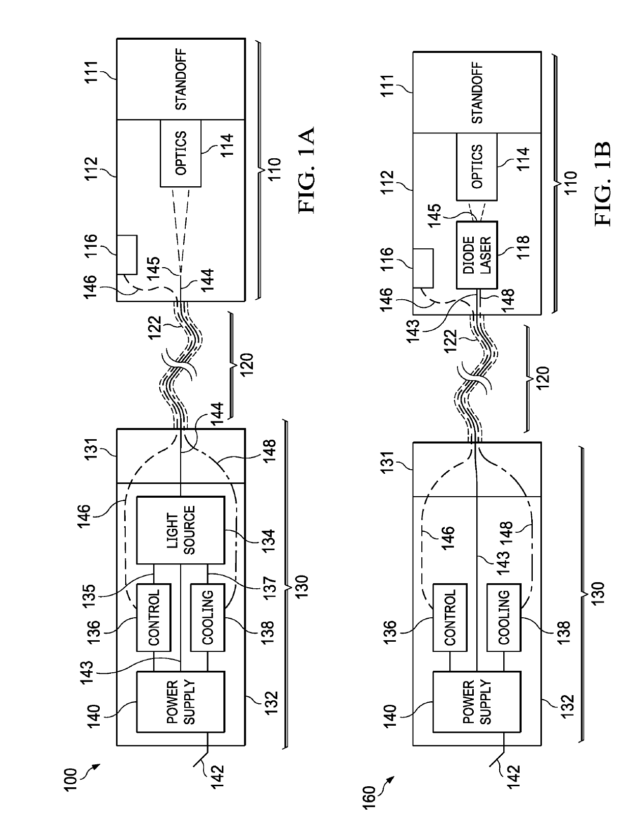
[0027]A schematic block diagram of a second embodiment for a system for laser treatment 160 is shown in FIG. 1B. This embodiment differs from the embodiment described in conjunction with FIG. 1A in that light source 134 is removed from system controller 130 and takes the form of a laser (in this case a diode laser 118) supported in housing 112 within handpiece 110. Treatment light emanates from emitting aperture 145 on diode laser 118 and is shaped and directed by optics 114. In this embodiment, no optical fiber connecting system controller 130 to handpiece 110 is required. Instead, electrical cable 146 is used to bring power and control signals to and from controller 136 to diode laser 118 within handpiece 110, as well as to return signals (which may include signals such as a control signal from trigger 116) to system controller 130 from handpiece 110. Cooling connection 148 can conduct cooling fluids from cooling system 138 through umbilical 120 to handpiece 110 in order to cool d...

third embodiment

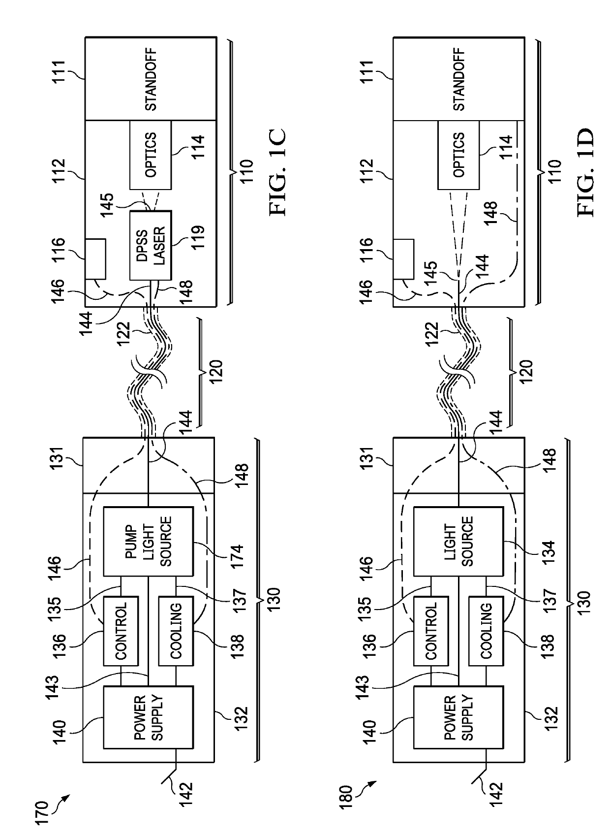
[0029]In FIG. 1C, a system for laser treatment 170 is shown, in which an optically-pumped laser such as a diode-pumped solid-state laser (DPSS laser) 119 is housed in handpiece 110. In this embodiment, power, control, and cooling systems are housed in system controller 130, but instead of a treatment light source, a pump light source 174 is housed in system controller 130. Pump light source 174 can be, for example, a diode laser emitting at a “pump wavelength,” i.e. a wavelength that is strongly absorbed by pump bands of a solid-state laser crystal. Light from pump light source 174 is conducted through optical fiber 144 into handpiece 110 and therein used to energize (“pump”) a crystal or glass element doped with lasing ions in the DPSS laser 119 that generates the treatment light. In this embodiment, rather than conducting light at the treatment wavelength, optical fiber 144 conducts light at the pump wavelength to the handpiece 110. Light generated by DPSS laser 119 emanates from ...


PUM


Abstract

A handpiece for laser treatment of a target surface on a patient, such as a skin surface, mitigates the effects of backscattered radiation at high optical power levels that can heat the handpiece to dangerous levels, as well as exposing practitioners and patients to the backscattered light and/or the handpiece structures heated thereby. A standoff affixed to the handpiece is configured to guide the handpiece position with respect to the target surface during use, such that the angle of incidence of treatment light is held near a predetermined angle that is not perpendicular to the target surface. This angle decreases the fraction of treatment light scattered directly back toward the handpiece, and the standoff may additionally be used to set a preferred distance to the target surface. Systems for laser treatment using a handpiece having these features, and methods for laser treatment using the handpiece are also provided.

Description

BACKGROUND OF THE INVENTION1. Field of the Invention[0001]The present invention relates generally to the field of treating tissue with electromagnetic radiation, and more particularly, to medical handpieces and related systems and methods for laser treatment that reduce the scattering of radiation back toward the handpiece.2. Description of the Related Art[0002]High-power lasers and similar high-intensity light sources are being used for an increasing number of therapeutic applications as well as medical surgical procedures. Many types and wavelengths of lasers are used for different applications, from dermatological to surgical. In many of the therapeutic applications, photochemical effects that stimulate biological processes are thought to be involved, as opposed to surgical applications that use primarily photothermal effects. For example, laser treatment is increasingly being applied to promoting wound healing, scar tissue reduction, and treatment of different types of musculosk...

Claims


Application Information

Patent Timeline
IPC IPC(8): A61B18/20A61B18/22
CPCA61B18/203A61B18/22A61B2018/00922A61B2018/00005A61B2018/00172A61B2018/00791A61B2018/2266A61B2017/00482A61B2018/00017A61B2018/00023A61B2018/2045A61B2018/00047A61B2018/202A61B2018/2025A61B2018/2255
Inventor MILLER, JEFFREYWINDEBANK, MICHAEL STUART WILLIAM
Owner BERKSHIRE PHOTONICS LLC
Why Eureka
Try Eureka