

Ultrasonic sensor, ultrasonic device, and method of manufacturing ultrasonic sensor
- Summary
- Abstract
- Description
- Claims
- Application Information
AI Technical Summary
Benefits of technology
Problems solved by technology
Method used
Image

Examples
first embodiment
[0038]Hereinafter, an ultrasonic device according to a first embodiment of the invention will be described.
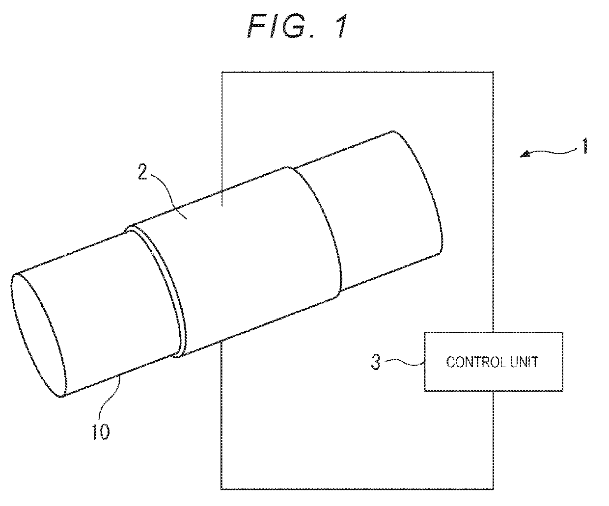
[0039]FIG. 1 is a diagram illustrating a schematic configuration of an ultrasonic device 1 according to the present embodiment.
[0040]As illustrated in FIG. 1, the ultrasonic device 1 according to the present embodiment includes an ultrasonic sensor 2 and a control unit 3 that controls a drive of the ultrasonic sensor 2.
[0041]The ultrasonic sensor 2 is attached to an object 10 and can be deformed depending on a shape of the object 10. For example, as illustrated in FIG. 1, in a case where the object 10 has a cylindrical shape such as a pipe, it is possible to wind the ultrasonic sensor 2 around the object 10.
[0042]By controlling the ultrasonic sensor 2 using the control unit 3, an ultrasonic wave can be transmitted from the ultrasonic sensor 2 to the object 10. By using the ultrasonic device 1, it is possible to perform various types of processing, such as internal inspection of...
second embodiment
[0094]Next, an ultrasonic sensor according to the second embodiment will be described.
[0095]The second embodiment is different from the first embodiment in that a resin layer is further provided on a side of the wall portion 23 opposite to the vibration plate in the ultrasonic sensor 2 according to the first embodiment. In the following description, the same reference numerals or symbols are attached to the items previously described, and description thereof will be omitted or simplified.
[0096]FIG. 9 is a schematic sectional view of the drive region Ar1 of an ultrasonic sensor 2A according to the present embodiment.
[0097]In the same manner as in the first embodiment, the ultrasonic sensor 2A according to the present embodiment includes the vibration plate 21 formed of a resin, the piezoelectric element 22, and the wall portion 23 formed of a resin. The ultrasonic sensor 2A further includes a resin layer 24 formed to cover a surface of the wall portion 23 opposite to the vibration pl...
modification example
[0105]The invention is not limited to the respective embodiments described above, and a configuration obtained by modifications, improvements, appropriate combination of the respective embodiments, and the like within a range in which the object of the invention can be attained are included in the invention.
[0106]In the ultrasonic sensor 2 according to the first embodiment described above, a configuration is used in which the wall portion 23 is provided on a side of the vibration plate 21 on which the piezoelectric element 22 is provided, but the configuration is not limited to this. That is, the wall portion 23 may be provided at a position surrounding the vibration portion 21A of the vibration plate 21.
[0107]The examples illustrated in FIGS. 10 to 13 are diagrams illustrating another example of the ultrasonic sensor according to the invention.
[0108]For example, as in an ultrasonic sensor 2B illustrated in FIG. 10, a configuration may be provided in which the piezoelectric element ...
PUM
 Abstract
Description
Claims
Application Information