Cooling device for vehicle

a technology for cooling devices and vehicles, applied in vehicle heating/cooling devices, vehicle components, propulsion parts, etc., can solve the problems of reducing the heat exchange efficiency of the second heat exchanger, reducing the power generation amount of the inverter, and suppressing the decrease in the power generation amount. , the effect of reducing the heat exchange efficiency of the condenser

Active Publication Date: 2019-08-22
TOYOTA JIDOSHA KK +1
View PDF0 Cites 24 Cited by
  • Summary
  • Abstract
  • Description
  • Claims
  • Application Information

AI Technical Summary

Benefits of technology

[0006]Incidentally, in JP 11-285106 A, a heat exchanger (radiator, condenser, or the like) is configured to be cooled by the electric fan. However, it is considered to cool the heat exchanger by combining a mechanical (engine driven) fan and an electric fan from viewpoints of reduction of power consumption while an engine is driven, and suppression of increase in size of a battery and the like.
[0007]Specifically, it is considered to employ a configuration in which a mechanical fan that rotates by a driving force of an engine being transmitted via a coupling is provided at a front end portion of the engine disposed in an engine compartment of a vehicle front portion, and a heat exchanger is disposed forward of the mechanical fan. With the configuration, by driving the mechanical fan while the engine is driven, it is possible to cool the heat exchanger by introducing outside air from a front grill not only while the vehicle is traveling but also while the vehicle is stopped.

Problems solved by technology

However, when the engine cooling heat exchanger is made relatively large in a limited space inside the engine compartment, there is a problem that it is difficult to dispose a plurality of heat exchangers for cooling an electric system to be next to the engine cooling heat exchanger in a vertical direction or a right-left direction of the vehicle.
In addition, the electric fan has a motor at the center of the electric fan in many cases; however, depending on a disposed position of the electric fan with respect to the mechanical fan, since the rigid coupling on the mechanical fan side and the rigid motor on the electric fan side come into contact with each other at the time of a forward collision, a case where it is difficult to secure collision energy absorption stroke is also assumed.
However, in the above configuration, while the engine is stopped, when the first electric fan is independently driven because only the first heat exchanger needs to be cooled, hot air heated by passing through the first heat exchanger and the engine cooling heat exchanger flows back, so that the heat exchange efficiency of the second heat exchanger may decrease.
Then, when such a decrease in the heat exchange efficiency occurs, it is needed to start the engine before the target time elapses depending on the object to be cooled by the first heat exchanger and the second heat exchanger, so that improvement in fuel consumption may not be achieved.
Although the inverter does not need to be positively cooled, when the second electric fan is independently driven in a case where the condenser needs to be cooled, such as cooling the inside of the vehicle using the air conditioner, as described above, the heat exchange efficiency of the radiator for cooling the inverter decreases and a power generation amount by the inverter decreases, so that there is a case where it is difficult to drive the electric system including the air conditioner.

Method used


Image

  • Cooling device for vehicle
  • Cooling device for vehicle
  • Cooling device for vehicle

Examples


Embodiment Construction

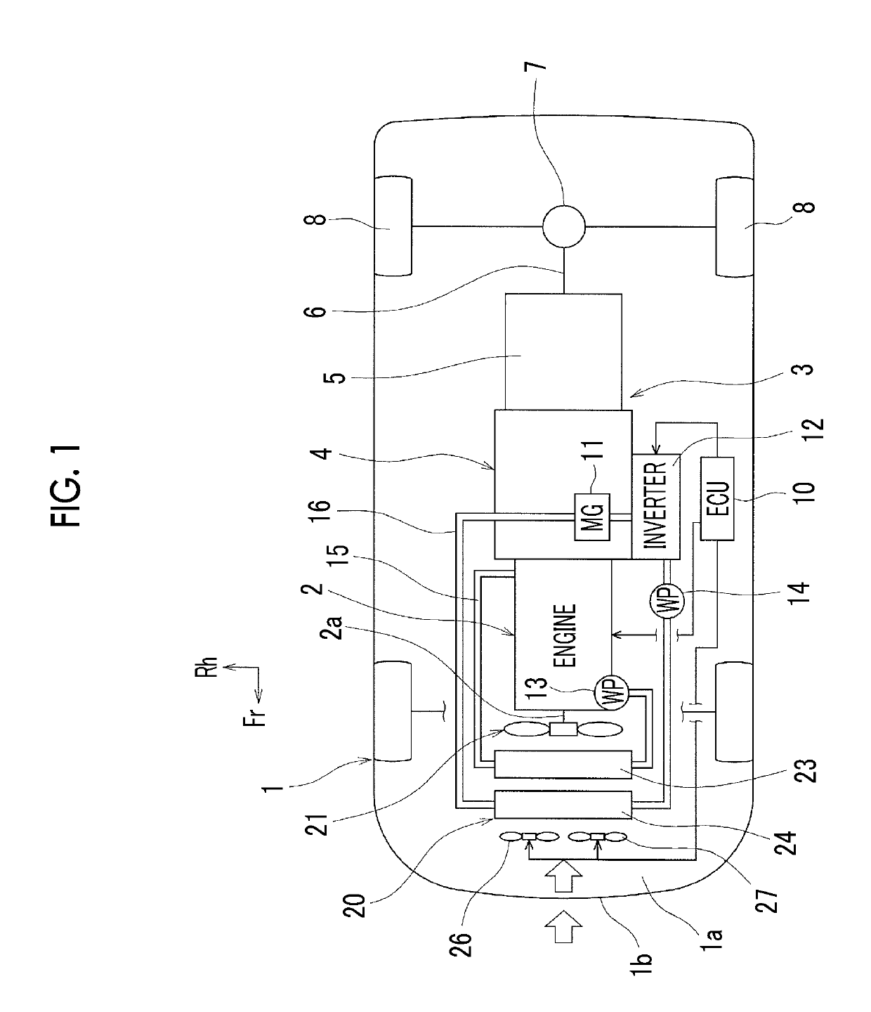
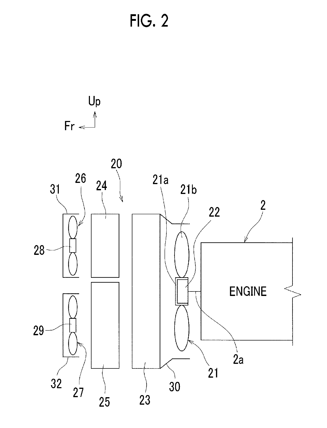
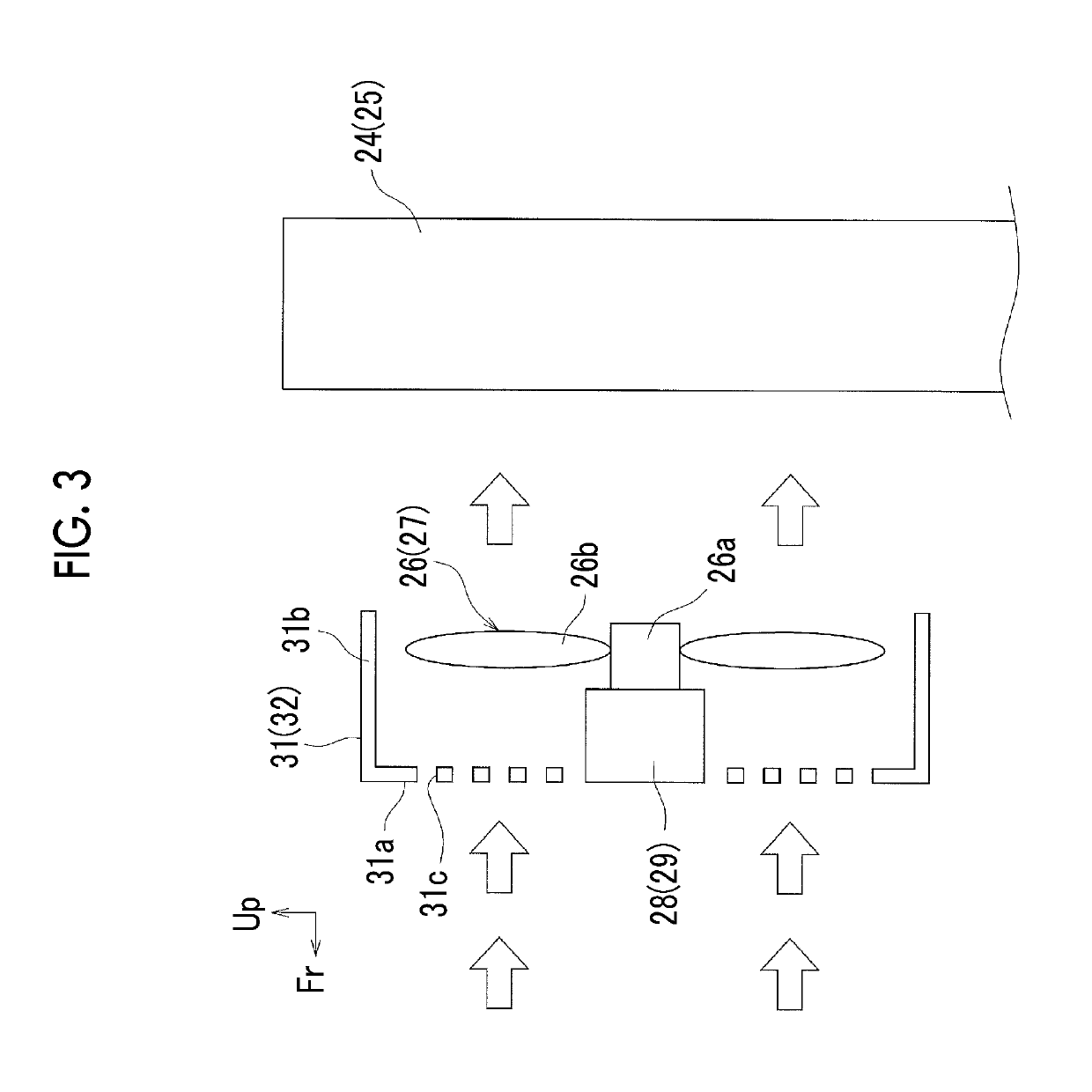
[0035]Hereinafter, an embodiment for carrying out the present disclosure will be described with reference to the drawings. In the drawings, an arrow Up indicates an upward direction, an arrow Fr indicates a front side of a vehicle (the front side in a front-rear direction of the vehicle), and an arrow Rh indicates a right side (the right side in a vehicle width direction).

[0036]Hybrid Vehicle

[0037]FIG. 1 is a diagram schematically showing a vehicle 1 on which a cooling device 20 for a vehicle according to the embodiment is mounted, and FIG. 2 is a side view schematically showing a main part of the cooling device 20 as seen from a left side in the vehicle width direction. The vehicle 1 is a front-engine and rear-drive (FR) vehicle, and includes a longitudinally-positioned engine 2 disposed in an engine compartment of a vehicle front portion 1a such that a crankshaft 2a extends in the front-rear direction of the vehicle, a power transmission device 3 provided between the engine 2 and ...


PUM


Abstract

A cooling device for a vehicle includes a mechanical fan configured to be driven by a driving force of the engine, an engine cooling heat exchanger disposed forward of the mechanical fan in a front-rear direction of the vehicle, a first heat exchanger and a second heat exchanger that are disposed forward of the engine cooling heat exchanger in the front-rear direction of the vehicle, a first electric fan that includes a first motor and cools the first heat exchanger, and a second electric fan that includes a second motor and cools the second heat exchanger. The first motor and the second motor are disposed forward of the first heat exchanger and the second heat exchanger, respectively, in the front-rear direction of the vehicle such that the first motor and the second motor do not overlap the coupling when viewed in a front direction of the vehicle.

Description

INCORPORATION BY REFERENCE[0001]The disclosure of Japanese Patent Application No. 2018-026628 filed on Feb. 19, 2018 including the specification, drawings and abstract is incorporated herein by reference in its entirety.BACKGROUND1. Technical Field[0002]The present disclosure relates to a cooling device for a vehicle and, more particularly, to a cooling device mounted on a hybrid vehicle.2. Description of Related Art[0003]A so-called hybrid vehicle that includes an engine and an electric motor and that travels by a driving force of one or both of the engine and the electric motor based on a predetermined driving condition is known from the related art.[0004]In addition to a cooling circuit for cooling the engine, a cooling device mounted on the hybrid vehicle is provided with a cooling circuit for cooling an electric system in order to cope with heat generation of the electric motor, an inverter, or the like (electric system), in many cases.[0005]For example, Japanese Unexamined Pat...

Claims


Application Information

Patent Timeline
Patent Type & Authority Applications(United States)
IPC IPC(8): B60H1/32B60H1/00
CPCB60H1/3205B60H1/00328B60H1/00464B60K1/00B60K11/06B60K2001/006B60K11/02
Inventor IKEDA, TETSUYANORISADA, KOUJINOGUCHI, MASAHIROMINAMIGAWA, MASATAKASHIBATA, MASASHISUEMATSU, JUNICHI
Owner TOYOTA JIDOSHA KK
Why Eureka
Try Eureka