
Error reduction and, or, correction in analog computing including quantum processor-based computing

Active Publication Date: 2019-08-29
D-WAVE SYSTEMS
View PDF0 Cites 12 Cited by
  • Summary
  • Abstract
  • Description
  • Claims
  • Application Information

AI Technical Summary

Benefits of technology

The patent describes a method for creating a putative Hamiltonian by applying a first function to a chosen nominal Hamiltonian or a set of terms of the status quo Hamiltonian. This method also involves using an L-BFGS optimization algorithm to minimize the difference between the logical target Hamiltonian and the putative Hamiltonian. Additionally, the patent describes a method for measuring the number of photons in each cavity by adjusting or setting inter-cavity couplers to either an ON or OFF state. The technical effects of these methods include increased efficiency and accuracy in creating a stable logical Hamiltonian and measuring the number of photons in each cavity.

Problems solved by technology

In quantum annealing thermal effects and other noise may be present to annealing.
However, due to the non-ideality of qubits, the bias of a qubit may affect neighboring qubits by inducing nearby couplers to cause indirect communicative coupling that is not characterized by the problem Hamiltonian.
This phenomenon is called background susceptibility which is a source of intrinsic control error that can lead to loss of fidelity, limit control precision, and sub-optimal solutions.
The errors resulting from background susceptibility tend to propagate when solving problems involving large clusters of qubits because the interactions or indirect communicative coupling is localized.
However, this solution is only feasible for certain types of cluster problems which include only a very small subset of qubits.
Generally, problems solved on a quantum processor will involve many qubits.
If a large number of qubits are clustered, significant errors may arise that cannot be adequately compensated for by hand.
Additionally, manual methods of addressing background susceptibility are vulnerable to random errors and can have inconsistent results.

Method used


Image

  • Error reduction and, or, correction in analog computing including quantum processor-based computing
  • Error reduction and, or, correction in analog computing including quantum processor-based computing
  • Error reduction and, or, correction in analog computing including quantum processor-based computing

Examples


Embodiment Construction

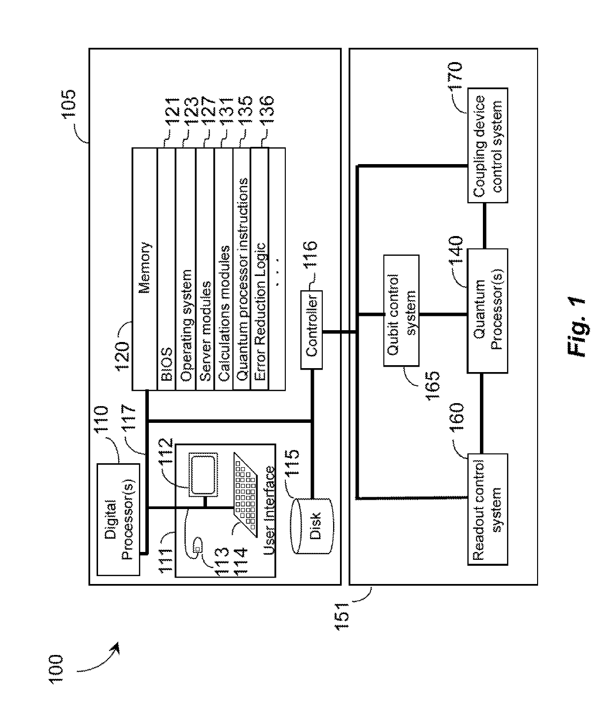
[0097]In the following description, some specific details are included to provide a thorough understanding of various disclosed embodiments. One skilled in the relevant art, however, will recognize that embodiments may be practiced without one or more of these specific details, or with other methods, components, materials, etc. In other instances, well-known structures associated with quantum processors, such as quantum devices, coupling devices, and control systems including microprocessors and drive circuitry have not been shown or described in detail to avoid unnecessarily obscuring descriptions of the embodiments of the present methods. Throughout this specification and the appended claims, the words “element” and “elements” are used to encompass, but are not limited to, all such structures, systems, and devices associated with quantum processors, as well as their related programmable parameters.

[0098]Unless the context requires otherwise, throughout the specification and claims...


PUM


Abstract

The systems, devices, articles, and methods described herein generally relate to analog computers, for example quantum processors comprising qubits, couplers, and, or cavities. Analog computers, for example quantum processor based computers, are the subject of various sources of error which can hinder operation, potentially reducing computational accuracy and speed. Sources of error can be broadly characterized, for example as i) a background susceptibility do to inherently characteristics of the circuitry design, ii) as an h / J ratio imbalance, iii) bit flip errors, iv) fidelity, and v) Anderson localization, and various combinations of the aforesaid.

Description

FIELD[0001]This disclosure generally relates to analog computing, for example quantum processor based computing, and in particular relates to reducing, correcting, or otherwise counteracting sources of error, via various hardware, and, or software techniques, designs, layouts, topologies, and architectures of analog processors, for example quantum processors, and to the operation of the same.BACKGROUNDQuantum Devices[0002]Quantum devices are structures in which quantum mechanical effects are observable. Quantum devices include circuits in which current transport is dominated by quantum mechanical effects. Such devices include spintronics, where electronic spin is used as a resource, and superconducting circuits. Both spin and superconductivity are quantum mechanical phenomena. Quantum devices can be used for measurement instruments, in computing machinery, and the like.Quantum ComputationCircuit Quantum Electrodynamic[0003]The field of quantum electrodynamics (QED) concerns interact...

Claims


Application Information

Patent Timeline
IPC IPC(8): G06N10/00G06F11/07
CPCG06N10/00G06F11/0793G06F11/0751G06F11/0736G06N5/01
Inventor BUNYK, PAUL I.KING, JAMESTHOM, MURRAY C.AMIN, MOHAMMAD H.SMIRNOV, ANATOLY YUYARKONI, SHEIRLANTING, TREVOR M.KING, ANDREW D.BOOTHBY, KELLY T. R.
Owner D-WAVE SYSTEMS
Learn More