
Inductor molded on an insulative plastic block

Inactive Publication Date: 2019-09-05
AJOHO ENTERPRISE
View PDF0 Cites 0 Cited by
  • Summary
  • Abstract
  • Description
  • Claims
  • Application Information

AI Technical Summary

Benefits of technology

The present invention is about a new type of inductor that is made by molding a plastic block with conductors on it. This new technology improves the quality and yield of the inductor's manufacturing, making it easier and more cost-effective to install. The conductors are formed on the plastic block using a laser direct structuring process. The magnetic cores of the inductor are placed in the plastic block, and the conductors are bonded to the contacts of a wire array using a continuous winding type coil loop. The direction and density of the conductors can be controlled to meet different needs, making it easier to produce the desired performance.

Problems solved by technology

(1) When the insulated wire is wound into a coil around the ferromagnetic core, uneven winding of the coil often occurs due to differences in manual winding distribution, and the stray capacitance on the inductor will be difficult to control, resulting in differences between the noise suppression capabilities of same specification coils. Thus, the exact distance between the coil windings must be controlled. Due to small core volume, the manual winding method takes a lot of man-hours. Further, manual winding is not practical for mass production so that the manufacturing cost cannot be reduced.
(2) In order to obtain a larger amount of inductance, the coil windings will generally be overlapped, however, the insulative layer of the enameled wire can easily be scratched during the winding process. Further, overlapping the coil windings of the insulated wire around the ferromagnetic core will greatly increase the dimension of the inductor, in sequence, the inductor will require a relatively larger circuit board mounting surface to affect the overall circuit layout. When bonding the leads of the coil of the inductor to a circuit board, the large volume of the coil can touch other electronic components on the circuit board, causing coil damage and affecting the electrical characteristics and charge and discharge functions of the inductor.
Therefore, the conventional inductor manufacturing method of manually winding the coil is time-consuming and labor-intensive and costly and cannot be mass-produced.
Further, inductor made according to the prior art design is bulky, occupies space on the circuit board, and affects the electrical characteristics and charging and discharging functions.

Method used


Image

  • Inductor molded on an insulative plastic block
  • Inductor molded on an insulative plastic block
  • Inductor molded on an insulative plastic block

Examples


Embodiment Construction

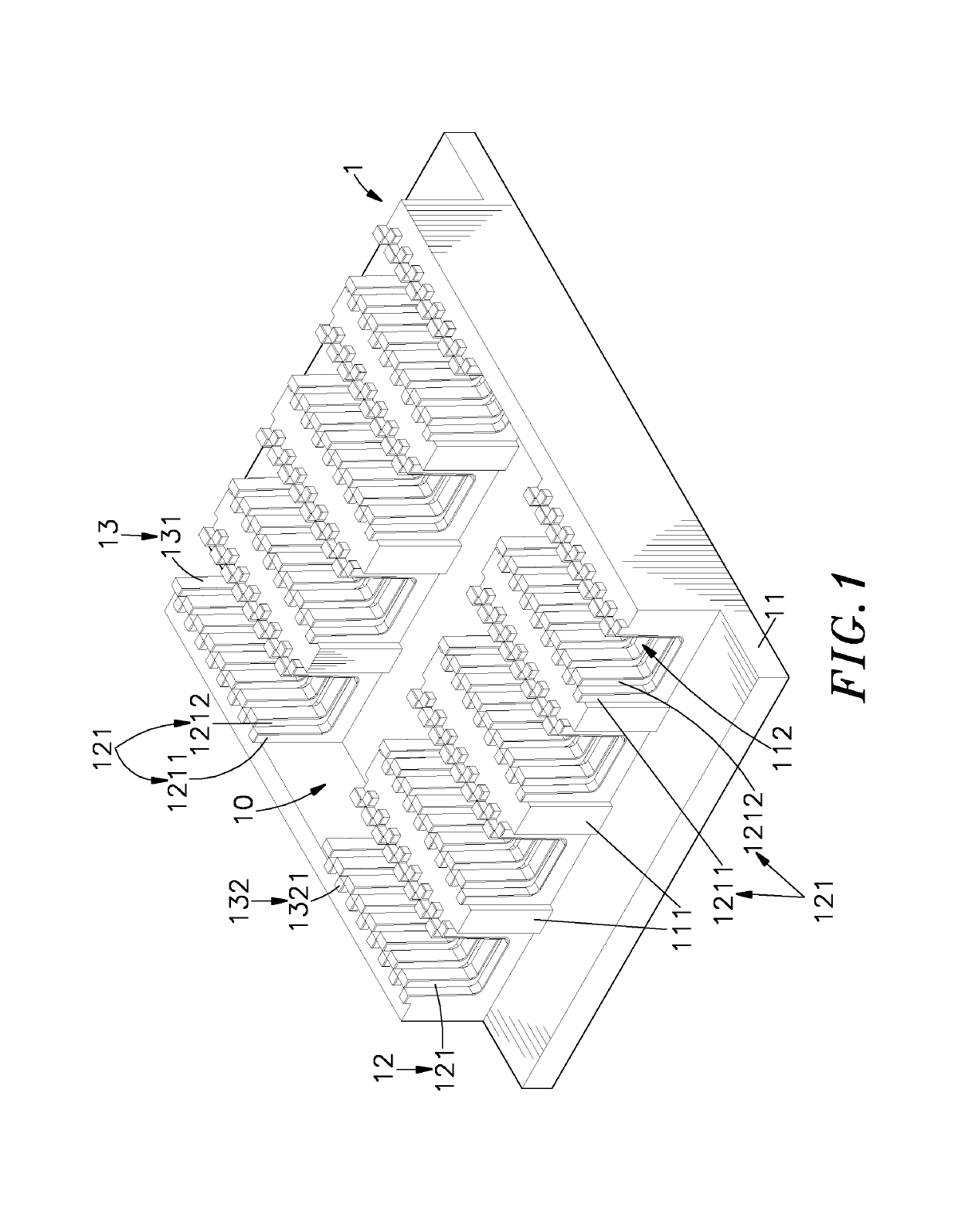
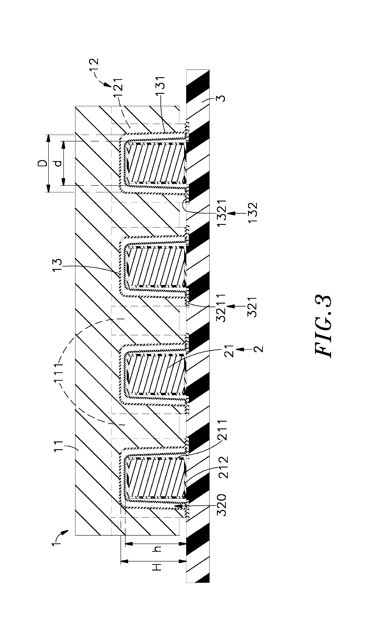
[0019]Referring to FIGS. 1-3, an inductor molded on an insulative plastic block in accordance with the present invention is shown. As illustrated, the inductor molded on an insulative plastic block comprises an insulative plastic block 1, a plurality of magnetic conductive components 2 and a connection carrier 3.

[0020]The insulative plastic block 1 comprises a block base 11 that is made from a plastic material in one piece by injection molding and defines a recessed open chamber 10 in a top side thereof, a plurality of partition plates 111 mounted in the recessed open chamber 10 and arranged in an array and dividing the recessed open chamber 10 into a plurality of parallel channels 112, a positioning unit 12 mounted in the channels 112, and conductors 13 formed on the positioning unit 12. The positioning unit 12 comprises a plurality of U-shaped plates 121 of two different widths and two different depths mounted in the channels 112 in a horizontally staggered manner with respective ...


PUM


Abstract

An inductor includes an insulative plastic block having a block base with a recessed open chamber, a positioning unit including odd-numbered rows of U-shaped plates and even-numbered rows of U-shaped plates arranged in a staggered manner in the recessed open chamber of the block base of the insulative plastic block, and a plurality of conductors respectively formed on the U-shaped plates and spaced from one another, each conductor having two opposite ends thereof respectively terminating in a lead outside the block base.

Description

[0001]This application is a Continuation-In-Part of co-pending application Ser. No. 15 / 972,814, filed on May 7, 2018, for which priority is claimed under 35 U.S.C. § 120, the entire contents of which are hereby incorporated by reference.[0002]This application claims the priority benefit of Application number 106137962 filed in Taiwan on Nov. 2, 2017.BACKGROUND OF THE INVENTION1. Field of the Invention[0003]The present invention relates to magnetic technologies and more particularly, to an inductor molded on an insulative plastic block, which comprises an insulative plastic block, rows of U-shaped plates of positioning unit mounted in the insulative plastic block in a staggered manner and conductors respectively formed on the U-shaped plates, magnetic cores of magnetic conductive components mounted in the insulative plastic block, and a connection carrier with a wire array thereof electrically bonded with the conductors to create with the magnetic cores a magnetic coil loop capable o...

Claims


Application Information

Patent Timeline
IPC IPC(8): H01F27/24H01F27/28H01F1/34
CPCH01F27/24H01F1/344H01F27/2823H01F27/2804H01F2027/2814H01F17/04H01F27/306
Inventor MO, CHIA-PINGLIU, YOU-CHI
Owner AJOHO ENTERPRISE
Features
  • Generate Ideas
  • Intellectual Property
  • Life Sciences
  • Materials
  • Tech Scout
  • Unparalleled Data Quality
  • Higher Quality Content
  • 60% Fewer Hallucinations
Learn More