Device and method for pressure-molding Anti-overheating csp fluorescent membrane

Active Publication Date: 2019-09-12
SOUTH CHINA UNIV OF TECH
View PDF0 Cites 0 Cited by
  • Summary
  • Abstract
  • Description
  • Claims
  • Application Information

AI Technical Summary

Benefits of technology

[0028](1) When the present invention is used to fix the LED chip and place the fluorescent membrane, a temperature of a clamp body for the LED clip is easily controlled, which prevents overheating due to long-term contact with a heat source, and can effectively prevent the fluorescent membrane from flowing prematurely, thereby reducing the operation difficulty of the procedure, and improving the yield rate of the procedure.
[0029](2) The elastic supporting structure of the device according to the present invention has an anti-overheating function, increases the operation time for fixing the LED chip and adjusting the fluorescent membrane, increases the operability of the process, and reduces the training cost of the operator.
[0030](3) The present invention is added with the stage of compressing the elastic supp

Problems solved by technology

The dispensing method implements molding by the constraint of a surface tension of the fluorescent resin itself, and is not adopted by CSP manufacturers basically since the consistency and uniformity thereof are poor.
At current, domestic CSP manufacturers have a low degree of automation in this process, mainly relying on manpower to clamp, load and unload the LED chip, and adjust the fluorescent membrane.
In this production process, there is often a process defect that the fluorescent membrane melts and flows due to overheating when the fluorescent membrane is not moulded.
This is because that it takes too long for the operator to load and unload materials and adjust the fl

Method used


Image

  • Device and method for pressure-molding Anti-overheating csp fluorescent membrane
  • Device and method for pressure-molding Anti-overheating csp fluorescent membrane
  • Device and method for pressure-molding Anti-overheating csp fluorescent membrane

Examples


Example

Embodiment 1

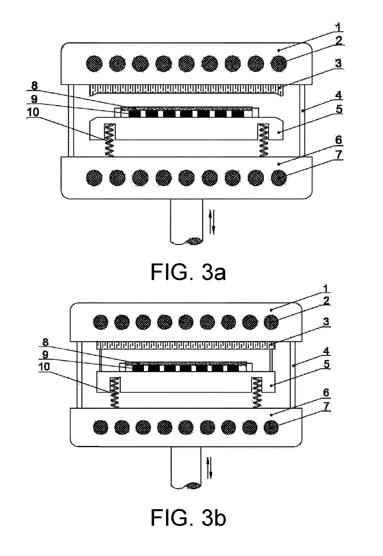
[0053]In the device used in this embodiment, an elastic supporting structure is a spring leaf, and the spring leaf has a stiffness of 10 N / cm along a pressure-molding direction. A contact of the spring leaf connected to a lower clamp 5 is line contact, and a contact area is 3% of an area of an upper surface of a lower pressing mould body 6. A contact of the spring leaf connected to the lower pressing mould body 6 is line contact, and a contact area is 3% of the area of the upper surface of the lower pressing mould body 6. A contact area of the bottom surface of the lower clamp 5 and the upper surface of the lower pressing mould body 6 is greater than 95% of an area of a lower bottom surface of the lower clamp 5 when the moulds are clamped.

[0054]The device for pressure-molding an anti-overheating CSP fluorescent membrane described above is adopted to mould a CSP fluorescent membrane.

[0055](1) Upper pressing mould and lower pressing mould heating devices are started to pre...

Example

Embodiment 2

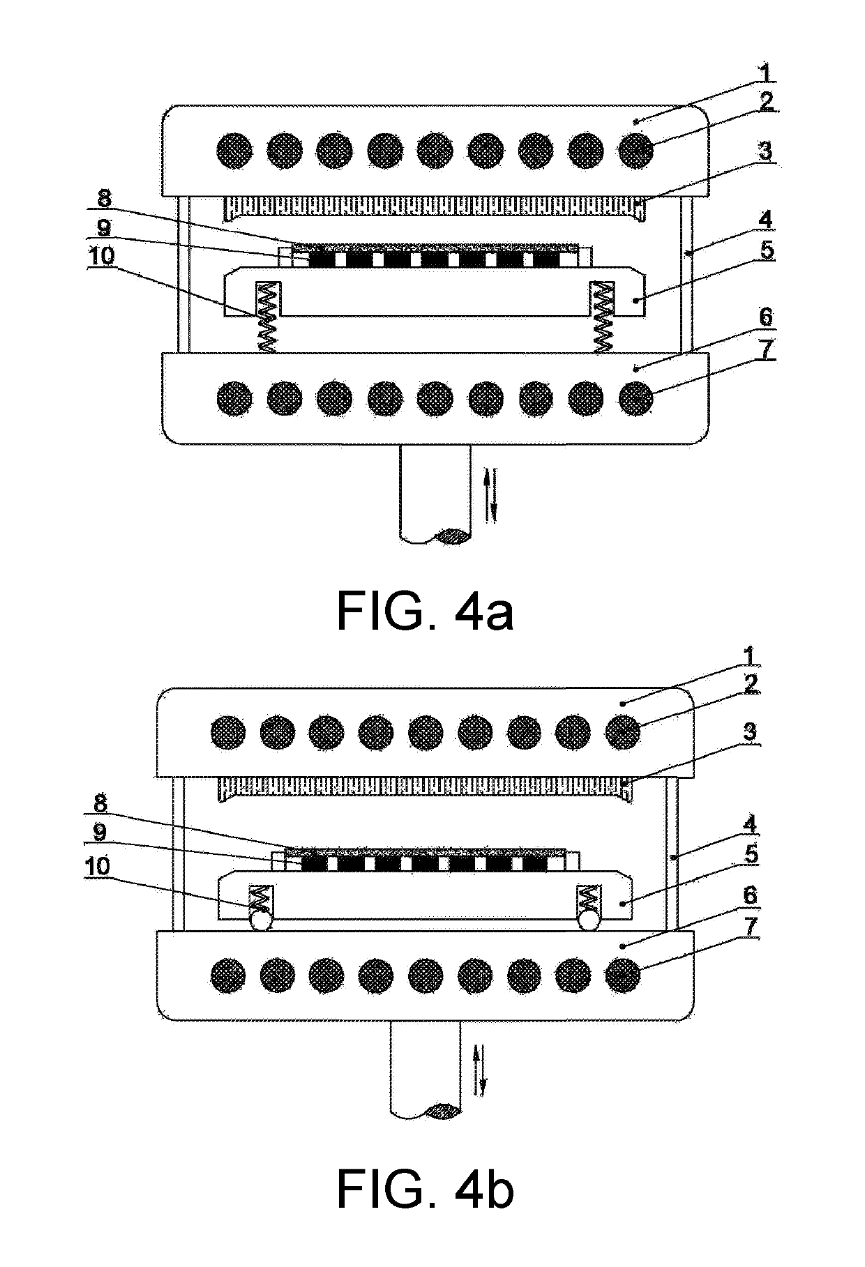
[0063]In the device used in this embodiment, an elastic supporting structure is a spring leaf, and the spring leaf has a stiffness of 25 N / cm along a pressure-molding direction. A contact of the spring leaf connected to a lower clamp 5 is line contact, and a contact area is 5% of an area of an upper surface of a lower pressing mould body 6. A contact of the spring leaf connected to the lower pressing mould body 6 is line contact, and a contact area is 5% of the area of the upper surface of the lower pressing mould body 6. A contact area of the bottom surface of the lower clamp 5 and the upper surface of the lower pressing mould body 6 is greater than 90% of an area of a lower bottom surface of the lower clamp 5 when the moulds are clamped.

[0064]The device for pressure-molding an anti-overheating CSP fluorescent membrane described above is adopted to mould a CSP fluorescent membrane.

[0065](1) Upper pressing mould and lower pressing mould heating devices are started to pre...

Example

Embodiment 3

[0073]In the device used in this embodiment, an elastic supporting structure is a spring leaf, and the spring leaf has a stiffness of 20 N / cm along a pressure-molding direction. A contact of the spring leaf connected to a lower clamp 5 is line contact, and a contact area is 5% of an area of an upper surface of a lower pressing mould body 6. A contact of the spring leaf connected to the lower pressing mould body 6 is line contact, and a contact area is 5% of the area of the upper surface of the lower pressing mould body 6. A contact area of the bottom surface of the lower clamp 5 and the upper surface of the lower pressing mould body 6 is greater than 93% of an area of a lower bottom surface of the lower clamp 5 when the moulds are clamped.

[0074]The device for pressure-molding an anti-overheating CSP fluorescent membrane described above is adopted to mould a CSP fluorescent membrane.

[0075](1) Upper pressing mould and lower pressing mould heating devices are started to pre...


PUM


Abstract

Disclosed are a device and a method for pressure-molding an anti-overheating CSP fluorescent membrane. The device comprises a frame, a mould pressing device, a force measuring device, a control device and a feeding device; and the mould pressing device comprises an upper pressing mould, an upper clamp, a lower pressing mould, a guide post, an elastic supporting structure, and a lower clamp. As the stage of pressing the elastic supporting structure is added to the course of pressure molding, a mould clamping force of the pressure molding increases in a relatively steady way, and a force impact of a mould clamping device is reduced, thereby easily determining an initial point for maintain temperature of the pressure molding. The present invention effectively prevents overheating caused by long-term and large-area contact between the lower clamp and the heating lower pressing mould, and avoids the process defect of premature melting of the fluorescent membrane due to overheating, thereby greatly improving the product consistency and yield rate of the CSP-package fluorescent membrane in the pressure molding process.

Description

TECHNICAL FIELD[0001]The present invention relates to the field of LED packaging technologies, and more particularly, to a device and a method for pressure-molding an anti-overheating CSP fluorescent membrane.DESCRIPTION OF RELATED ART[0002]With the LED technologies developed and cost controlled, the packaging volume of a LED device is getting smaller and smaller, and a power density thereof is continuously increasing. A Chip Scale Package (CSP) device can eliminate gold wires, requires an extremely small substrate or even does not need a substrate, so that the device size is greatly reduced, and the package cost is decreased by up to 20% in the meanwhile. In addition, the thermal resistance of the CSP device is also reduced, the light-emitting density of the CSP is improved, and the small size, thin depth and light weight characteristics of the CSP greatly enhance the design and application flexibility thereof. Therefore, CSP package is widely used in different fields, and a market...

Claims


Application Information

Patent Timeline
IPC IPC(8): F21K9/90H01L33/48F21K99/00
CPCF21K99/00F21K9/90H01L33/48H01L33/505H01L21/68785H01L2933/0041Y02P40/57
Inventor LI, ZONGTAOLIN, QINGHONGTANG, YONGYU, SHUDONGWANG, HUIYULIANG, GUANWEILU, LONGSHENG
Owner SOUTH CHINA UNIV OF TECH
Why Eureka
Try Eureka