Objective lens attachment

Inactive Publication Date: 2019-09-26
LIG NANOWISE LTD
View PDF0 Cites 1 Cited by
  • Summary
  • Abstract
  • Description
  • Claims
  • Application Information

AI Technical Summary

Benefits of technology

[0048]The apparatus may comprise illumination means operable to generate light to illuminate the sample. The generated light may be monochrome or broad spectrum as required or desired. The illumination means may be operable to illuminate the sample in reflection or transmission modes. In embodiments where the illumination means are operable to illuminate the sample in reflection, the apparatus may be provided with a restricted aperture between the illumination means and the objecti

Problems solved by technology

The use of a microsphere rather than a truncated microsp

Method used


Image

  • Objective lens attachment
  • Objective lens attachment
  • Objective lens attachment

Examples


Embodiment Construction

[0065]In order that the invention may be more clearly understood embodiments thereof will now be described, by way of example only, with reference to the accompanying drawings, of which:

[0066]FIG. 1 shows an embodiment of an objective lens attachment for a microscope according to the present invention;

[0067]FIG. 2 shows the objective lens attachment of FIG. 1 in position for attachment to the objective lens of a microscope;

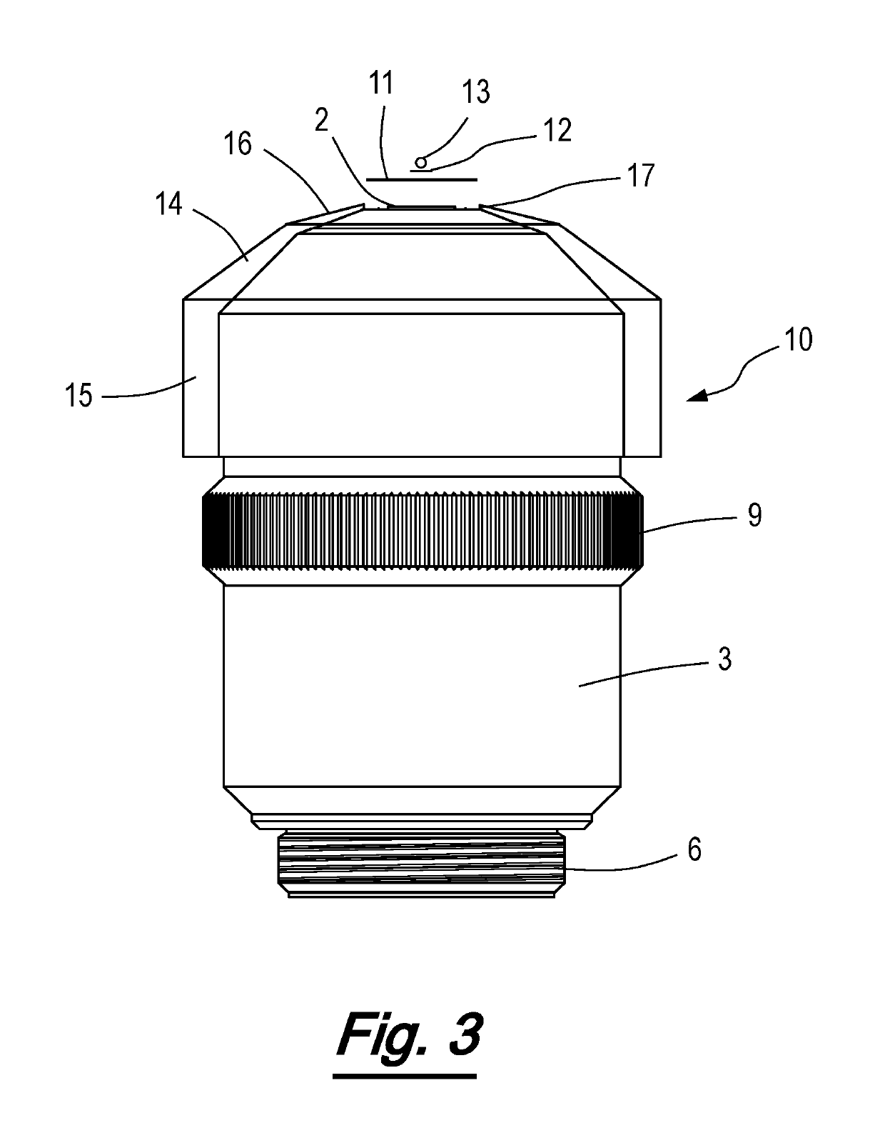
[0068]FIG. 3 shows the objective lens attachment of FIG. 1 attached to the objective lens of a microscope;

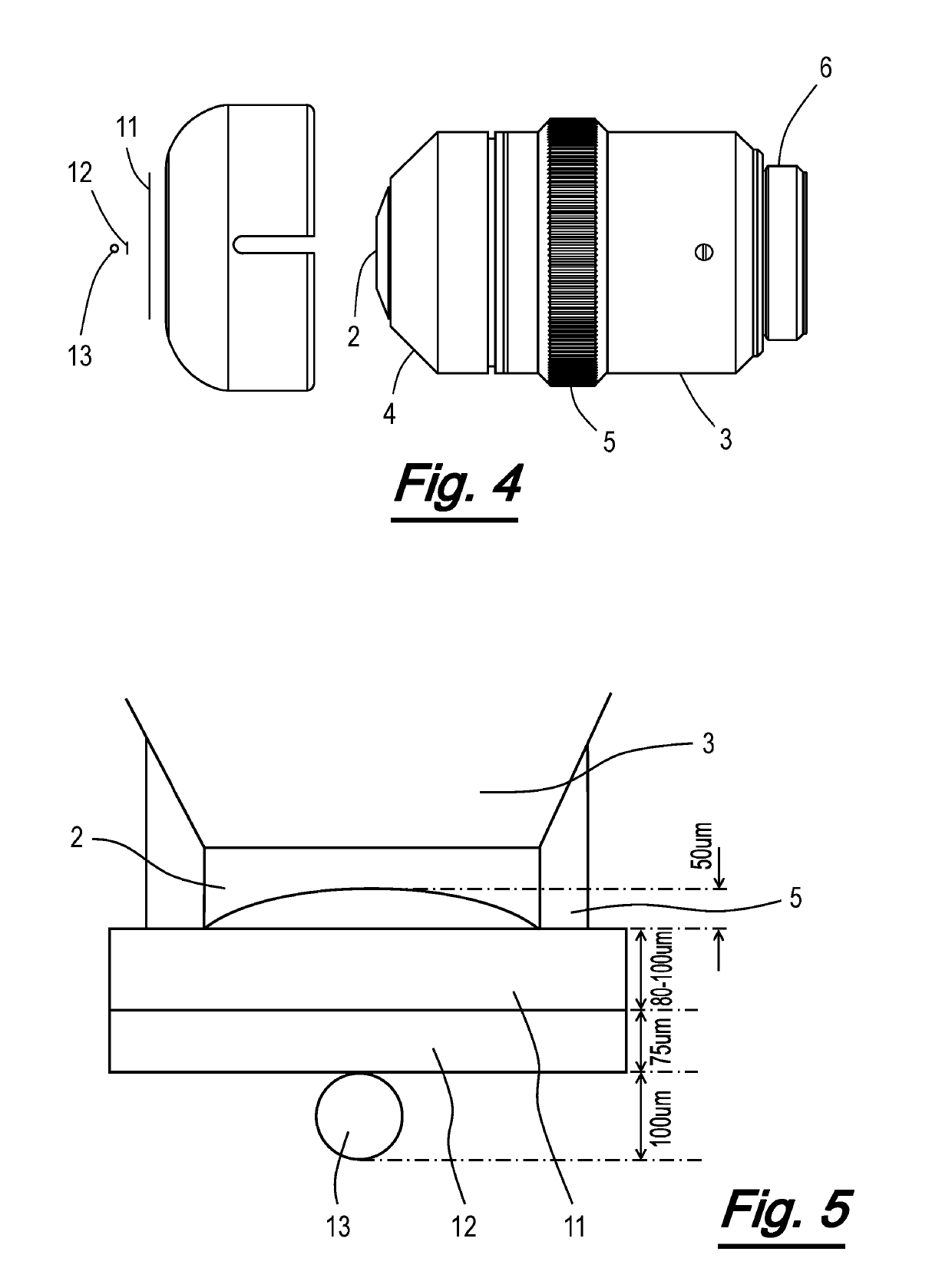
[0069]FIG. 4 shows another embodiment of an objective lens attachment for a microscope according to the present invention;

[0070]FIG. 5 is a schematic illustration of the positioning of the optical elements of an embodiment of the objective lens attachment of the present invention in relation to the objective lens;

[0071]FIG. 6 is a schematic illustration of the positioning of the optical elements of an embodiment of the objective lens attachment of the present ...


PUM


Abstract

An objective lens attachment (10) positions a microsphere lens (13) between the objective lens (2) and a sample. The attachment (10) is adapted to position the microsphere lens at a desired separation from the objective lens (2) to provide optimal super resolution imaging performance. The objective lens attachment (10) comprises a cap (14) having a substantially tubular body (15) and a top (16). The top (16) is provided with a contact surface (17) surrounding an aperture (18). The aperture (18) is aligned with the objective lens when the cap (14) is fitted to the objective lens housing (3). A support sheet (11) formed from optically clear material is affixed to the cap (14). Upon the support sheet (11) is provided an adhesive layer (12). Affixed to the adhesive layer (12) is a microsphere lens (13), the microsphere lens being aligned with the centre of the objective lens (2).

Description

TECHNICAL FIELD OF THE INVENTION[0001]The present invention relates to an objective lens attachment. In particular, the invention relates to an objective lens attachment comprising a single microsphere lens. The objective lens attachment may be suitable for super resolution microscopy, imaging or fabrication. The present invention further relates to the manufacture and use of such objective lens attachments.BACKGROUND TO THE INVENTION[0002]Conventional optical microscopic imaging resolution has a theoretical limit of approximately 200 nm within the visible light spectrum due to the far-field diffraction limit. As a result, conventional optical microscopic imaging is not suitable for imaging subjects having structures smaller than this limit, for example live viruses (typically 5-150 nm, with some up to 300 nm). In order to image such structures beyond the optical diffraction limit, other techniques have been used.[0003]Transmission electron microscopy (TEM) and scanning electron mic...

Claims


Application Information

Patent Timeline
IPC IPC(8): G02B21/02G02B21/00G02B3/00
CPCG02B21/02G02B21/002G02B3/0087
Inventor STANESCU, SORINGUO, WEILI, LIN
Owner LIG NANOWISE LTD
Why Eureka
Try Eureka