Vehicle thermal systems low to high quality energy management, storage, recovery, and optimization

a technology for energy management and vehicles, applied in the direction of secondary cell servicing/maintenance, battery/fuel cell control arrangement, electrochemical generators, etc., can solve the problems of relative complex series of circuits, thermal energy is generated in large quantities, and thermal energy surplus is generated, so as to prevent condenser icing

Active Publication Date: 2019-10-03
GM GLOBAL TECH OPERATIONS LLC
View PDF8 Cites 13 Cited by
  • Summary
  • Abstract
  • Description
  • Claims
  • Application Information

AI Technical Summary

Benefits of technology

[0003]However, even though ICEs have, and will likely continue to become, more and more efficient, substantial quantities of thermal energy are generated by the ICEs, a significant amount of which is usually rejected to the vehicle's surroundings. That is, in an ICE-powered vehicle, a surplus of thermal energy is generated by the ICE, and cannot be effectively or efficiently contained within the motor vehicle. Thus, a significant amount of so-called “high quality” thermal energy is often rejected from the motor vehicle to the atmosphere. In an attempt to mitigate the inefficient use of ICEs, and to lower emissions, reduce environmental impact, and improve responsiveness, smoothness, NVH, and operator comfort, motor vehicles are increasingly relying upon electrical power for both motivation as well as management of the passenger compartment environment. However, the increasing use of electrical power, as is produced by innovative propulsion systems such as hybrid systems, batteries, fuel cells and the like, has dramatically reduced the amount, and the quality of the thermal energy generated by vehicles equipped with such innovative propulsion systems.
[0004]Accordingly, while traditional systems and methods of thermal management originally designed for ICE systems can be applied to innovative propulsion systems, the surplus of thermal energy is much smaller than in an ICE system. Therefore, while traditional systems and methods of thermal management can operate for their intended purpose in ICE systems, there is a need for improved systems and methods of thermal management for vehicles in which the use of ICEs is reduced, and / or eliminated entirely. Thus, there is a need in the art for new and improved thermal management systems and methods which efficiently collect, store, and distribute thermal energy to vehicle systems that need such energy, while reducing hardware cost and complexity, improving reliability, and offering improved safety and redundancy, and reduced range anxiety for motor vehicle operators.SUMMARY
[0009]In yet another aspect of the present disclosure determining if thermal energy is needed further includes selectively operating a condenser. continuously operating the condenser, monitoring a condenser efficiency, and preventing condenser icing by exchanging thermal energy between dissimilar thermal fluid loops.

Problems solved by technology

The scavenging functions are often performed on dedicated heating, cooling, or electrical circuits, leading to a relatively complex series of circuits, many of which function almost entirely independent of one another.
However, even though ICEs have, and will likely continue to become, more and more efficient, substantial quantities of thermal energy are generated by the ICEs, a significant amount of which is usually rejected to the vehicle's surroundings.
That is, in an ICE-powered vehicle, a surplus of thermal energy is generated by the ICE, and cannot be effectively or efficiently contained within the motor vehicle.
Thus, a significant amount of so-called “high quality” thermal energy is often rejected from the motor vehicle to the atmosphere.
However, the increasing use of electrical power, as is produced by innovative propulsion systems such as hybrid systems, batteries, fuel cells and the like, has dramatically reduced the amount, and the quality of the thermal energy generated by vehicles equipped with such innovative propulsion systems.
Accordingly, while traditional systems and methods of thermal management originally designed for ICE systems can be applied to innovative propulsion systems, the surplus of thermal energy is much smaller than in an ICE system.

Method used


Image

  • Vehicle thermal systems low to high quality energy management, storage, recovery, and optimization
  • Vehicle thermal systems low to high quality energy management, storage, recovery, and optimization
  • Vehicle thermal systems low to high quality energy management, storage, recovery, and optimization

Examples


Embodiment Construction

[0033]The following description is merely exemplary in nature and is not intended to limit the present disclosure, application, or uses.

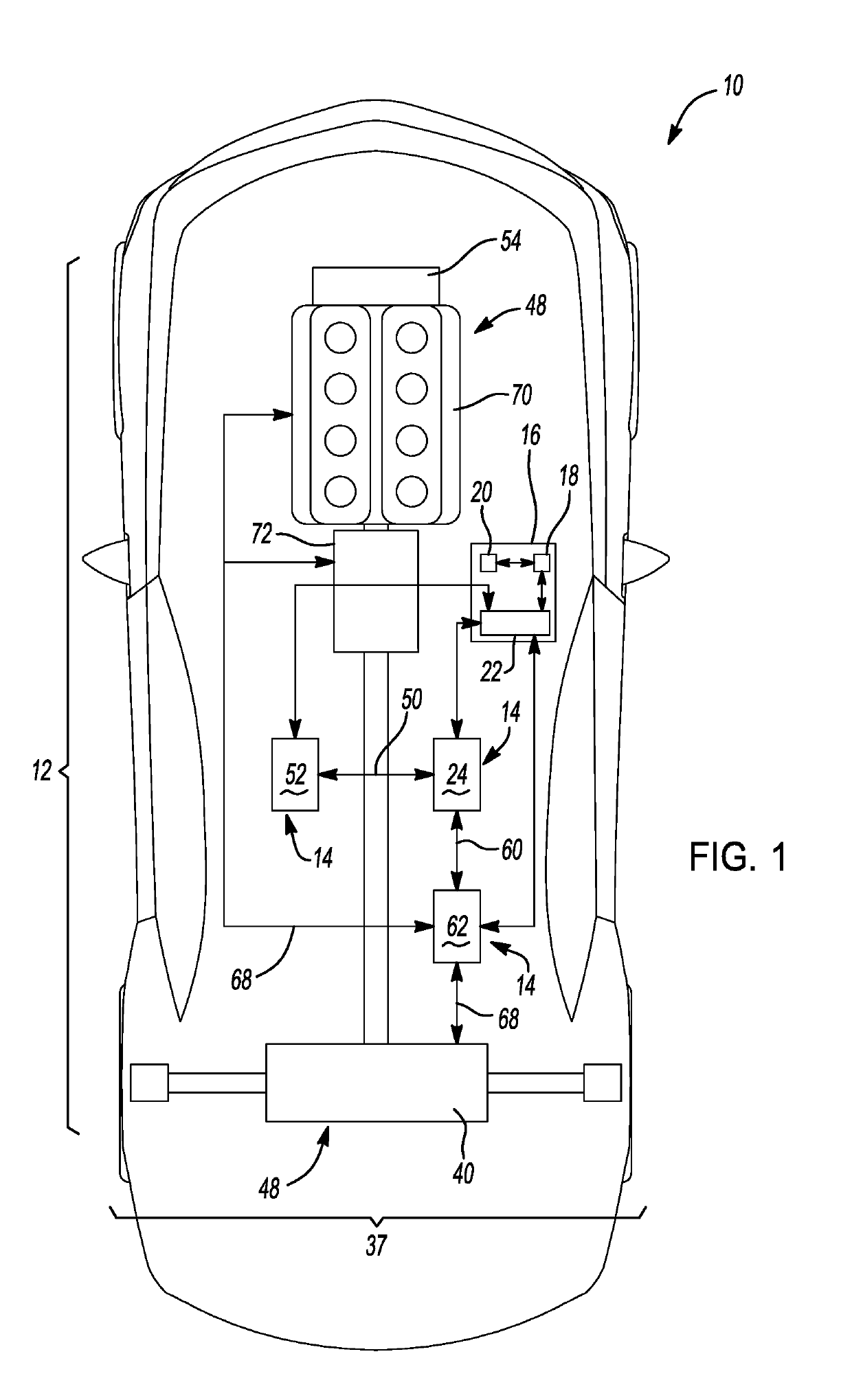
[0034]Referring to FIG. 1, a motor vehicle is shown and indicated generally by reference number 10. While the motor vehicle 10 is depicted as a car, it should be understood that the motor vehicle 10 may be a car, a truck, an SUV, a van, a semi, a tractor, a bus, a go-kart, or any other such motor vehicle 10 without departing from the scope or intent of the present disclosure. The motor vehicle 10 is equipped with a thermal management system 12. In broad terms, the thermal management system 12 operates to selectively transport thermal energy from a heat source within the thermal management system 12 to a heat sink in the thermal management system 12, or from a heat source or a heat sink to a location within the thermal management system 12 where the thermal energy is needed. The thermal management system 12 includes a plurality of dissimilar thermal ...


PUM


Abstract

A method for continuously managing thermal energy in a motor vehicle includes initializing a continuous thermal energy management control loop within a controller disposed in the motor vehicle, calculating a quantity of stored energy in a thermal management system equipped to the motor vehicle, calculating a quantity of thermal energy waste in the thermal management system, determining if thermal energy is needed within a component of the thermal management system, selectively generating thermal energy, selectively transporting thermal energy to the component of the thermal management system, determining a thermal storage capacity of the thermal management system, determining if a thermal energy deficit exists within the thermal management system, and directing a flow of a thermal energy carrying liquid to a thermal energy reservoir.

Description

INTRODUCTION[0001]The statements in this section merely provide background information related to the present disclosure, and may not constitute prior art.[0002]The present disclosure relates to motor vehicle thermal management systems, and more specifically to systems and methods for controlling the operation of thermal energy sources and sinks within a motor vehicle. Emissions standards, environmental concerns, and operator perceptions of responsiveness, smoothness and noise, vibration, and harshness (NVH), as well as operator comfort dictate many of the ways in which thermal energy within a motor vehicle is controlled. Traditionally, efficiencies have been sought within the confines of the internal combustion engines (ICE) functioning as prime movers for motor vehicles. Such advances have generally taken the form of improving combustion efficiency (maximizing combustion energy conversion into motive force), scavenging combustion thermal energy to run HVAC functions, scavenging br...

Claims


Application Information

Patent Timeline
Patent Type & Authority Applications(United States)
IPC IPC(8): B60L11/18B60L7/18B60H1/00
CPCB60L2240/425B60H1/00385B60H2001/00307B60L58/24B60H1/00278B60L2240/36B60L7/18B60H1/00642H01M10/613H01M10/615H01M10/625B60K11/02B60H1/00921B60H2001/00928B60H2001/00949B60H1/00885B60L1/003B60L1/02H01M10/44H01M10/66Y02T10/64Y02T10/70Y02E60/10
Inventor GONZE, EUGENE V.ZIEHR, LAWRENCE P.KETKAR, SATISH P.CARLSON, MICHAEL H.
Owner GM GLOBAL TECH OPERATIONS LLC
Why Eureka
Try Eureka