Method of managing imprint apparatus, imprint apparatus, method of managing planarized layer forming apparatus, and method of manufacturing article

Active Publication Date: 2019-10-03
CANON KK
View PDF0 Cites 1 Cited by
  • Summary
  • Abstract
  • Description
  • Claims
  • Application Information

AI Technical Summary

Benefits of technology

The present invention provides a way to make sure when to replace a chemical filter in an imprint machine. This helps to make the process more accurate.

Problems solved by technology

The impurity removal performance of the chemical filter decreases as it is used, and the filter reaches the end of its life.
If the chemical filter is not replaced and continues to be used with the decreased impurity removal performance, the substrate surface will be contaminated with impurities.
This impairs the fluidity of an imprint material so the imprint material is not uniformly filled between the substrate and the mold, resulting in generation of pattern defects.
If the chemical filter is replaced periodically, it will be replaced before it reaches the end of its life, resulting in waste.
In this case, a sample gas is generally collected and analyzed, but the analysis takes a long time and the cost of analysis increases.
However, in an imprint apparatus, the wavelength of a light source used for curing an imprint material is longer than those of an KrF laser or an ArF laser, and the energy is small.
Therefore, fogging of an optical component hardly occurs so that it is difficult to determine the degradation of the chemical filter by measuring fogging.

Method used


Image

  • Method of managing imprint apparatus, imprint apparatus, method of managing planarized layer forming apparatus, and method of manufacturing article
  • Method of managing imprint apparatus, imprint apparatus, method of managing planarized layer forming apparatus, and method of manufacturing article
  • Method of managing imprint apparatus, imprint apparatus, method of managing planarized layer forming apparatus, and method of manufacturing article

Examples


first embodiment

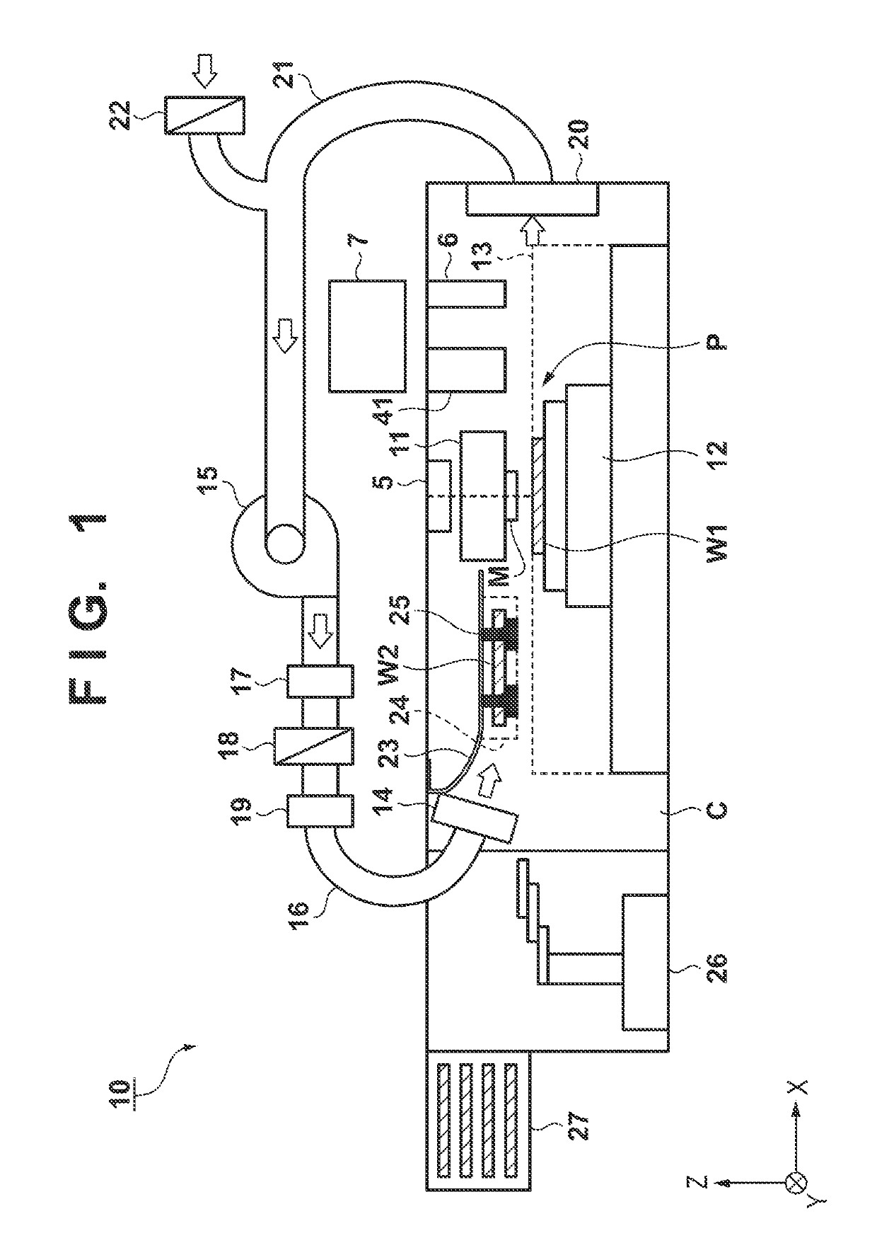
[0022]FIG. 1 is a view showing the arrangement of an imprint apparatus 10 according to the first embodiment. Note that in this specification and the accompanying drawings, directions are shown in an X-Y-Z coordinate system in which directions parallel to the surface of a substrate W are assumed to be on an X-Y plane. In this embodiment, the imprint apparatus 10 employs a photo-curing method for curing the imprint material with irradiation of ultraviolet light as the imprint material curing method. Note that the imprint apparatus 10 is not limited to this, and it can employ, for example, a heat-curing method which uses a thermosetting imprint material and cures it by heating.

[0023]A mold M having a pattern formed thereon is conveyed by a mold conveying system (not shown) and held by a mold head 11. The mold head 11 includes a drive mechanism that holds the mold M and drives it in the Z-axis direction. The mold head 11 may further include a drive mechanism that holds the mold M and dr...

second embodiment

[0042]FIG. 5 is a view showing the arrangement of an imprint apparatus 10 according to the second embodiment. The same components as in FIG. 1 are denoted by the same reference numerals, and their descriptions will be omitted.

[0043]The retaining portion 24 is provided inside the chamber C in FIG. 1, but a retaining portion 28 is provided outside a chamber C in FIG. 5. The imprint apparatus 10 shown in FIG. 5 includes an air supply path 32 branching off from an air supply path 16, and the distal end of the air supply path 32 is connected to a blowout portion 30 provided at the supply port of the retaining portion 28.

[0044]On the side facing the blowout portion 30 of the retaining portion 28, an exhaust portion 31 is provided. An exhaust path 33 connected to the exhaust portion 31 is merged to an exhaust path 21. With this arrangement, the gas exhausted from the exhaust portion 31 is returned to the suction port of a blower 15 via the exhaust path 33 and the exhaust path 21.

[0045]Here...

third embodiment

[0046]FIG. 6 is a view showing the arrangement of an imprint apparatus 10 according to the third embodiment. The same components as in FIG. 1 are denoted by the same reference numerals, and their descriptions will be omitted.

[0047]The retaining portion 24 is provided inside the chamber C in FIG. 1, but no retaining portion is provided in FIG. 6. In this case, a test mold M2 (blank mold) is set on a mold head 11, and a test substrate W2 is held on a stage 12. In this state, it is retained for the predetermined time assumed for an imprint process. Thereafter, the processing after S10 in FIG. 4 is executed and the state of a chemical filter 18 is evaluated.

[0048]According to this embodiment, a test substrate cannot be retained during a process for processing a substrate for mass production, but the state of the chemical filter 18 can be evaluated without separately providing the retaining portion 24.


PUM


Abstract

There is provided a method of managing an imprint apparatus that comprises a processor configured to execute an imprint process for forming a layer of an imprint material on a substrate by using a mold, a chamber configured to accommodate the processor, and a chemical filter configured to remove a chemical impurity contained in a gas flowing inside the chamber. The method comprises retaining a test substrate inside the chamber during execution of the imprint process, forming a layer of an imprint material on the test substrate by executing the imprint process on the test substrate by the processor after the retaining, inspecting the layer formed on the test substrate in the forming, and determining whether or not to replace the chemical filter based on an inspection result obtained in the inspecting.

Description

BACKGROUND OF THE INVENTIONField of the Invention[0001]The present invention relates to a method of managing an imprint apparatus, an imprint apparatus, a method of managing a planarized layer forming apparatus, and a method of manufacturing an article.Description of the Related Art[0002]An imprint technique for forming an imprint material pattern on a substrate by using a mold is being put into practice as one of lithography techniques each for manufacturing an article such as a semiconductor device. As for the imprint technique, there has been proposed a photo-curing method which cures an imprint material by using light. In this method, a mold is brought into contact with an imprint material on a substrate and the imprint material is irradiating with light in this state so that the imprint material is cured. After that, the mold is separated from the cured imprint material.[0003]The space in which such an imprint process is executed is formed in a clean chamber. The inside of the ...

Claims


Application Information

Patent Timeline
IPC IPC(8): G03F7/00G03F7/20
CPCB82Y40/00B82Y10/00G03F7/0002G03F7/70716G03F7/70483G03F7/70308G03F9/7042
Inventor AICHI, SHINTARO
Owner CANON KK
Why Eureka
Try Eureka