Tire comprising a tread containing circumferential reinforcing elements in the sublayer

a technology of circumferential reinforcement and sublayer, which is applied in the field of tires, can solve the problems of conflicting with the objective of minimizing rolling resistance, poor drift thrust response of the tyre when subjected to stress, and the tyre made according to this teaching does not achieve any progress in terms of performance properties

Pending Publication Date: 2019-10-10
MICHELIN & CO CIE GEN DES ESTAB MICHELIN
View PDF0 Cites 2 Cited by
  • Summary
  • Abstract
  • Description
  • Claims
  • Application Information

AI Technical Summary

Problems solved by technology

However, the lower the stiffness of the sublayer, the poorer the drift thrust response of the tyre is when subjected to stress by the vehicle turning.
However, this may conflict with the objective of minimizing the rolling resistance.
However, a tyre made according to this teaching does not achieve any progress in terms of the balance of performance properties.
With this in mind, while the use of a less stiff rubber tread compound promotes grip, it also promotes shearing of the tread pattern blocks when the tyre needs to oppose an axially oriented force, and this causes the tread pattern blocks to rock; that generates greatly raised pressures on the leading edges of the tread pattern blocks; these greatly raised pressures in turn generate very significant heating.
These raised pressures and this heating can contribute towards very rapid damage to the tread of the tyre and towards non-optimal exploitation of the grip potential of the tread compound.
The reinforcement of the circumferential grooves that is thus produced makes it possible to increase the drift thrust of the tyre, but the presence of a stiff compound in the groove bottom makes it difficult to mould the wear indicators.
None of these teachings makes it possible to use high-grip rubber compounds for the tread without leading either to rapid wearing when the tyre is heavily loaded or to too great a degradation in the rolling resistance of the tyre.

Method used


Image

  • Tire comprising a tread containing circumferential reinforcing elements in the sublayer
  • Tire comprising a tread containing circumferential reinforcing elements in the sublayer
  • Tire comprising a tread containing circumferential reinforcing elements in the sublayer

Examples


Embodiment Construction

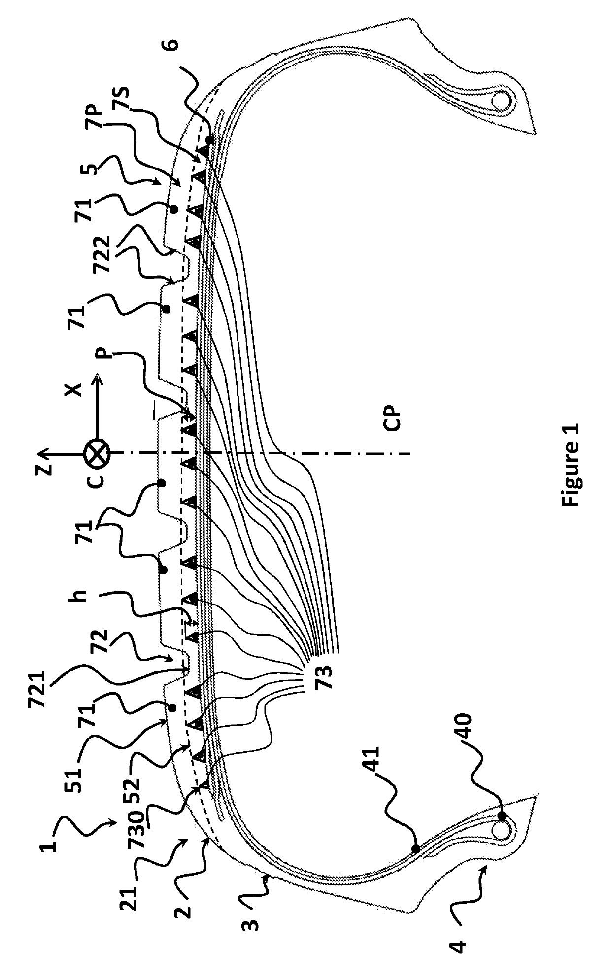
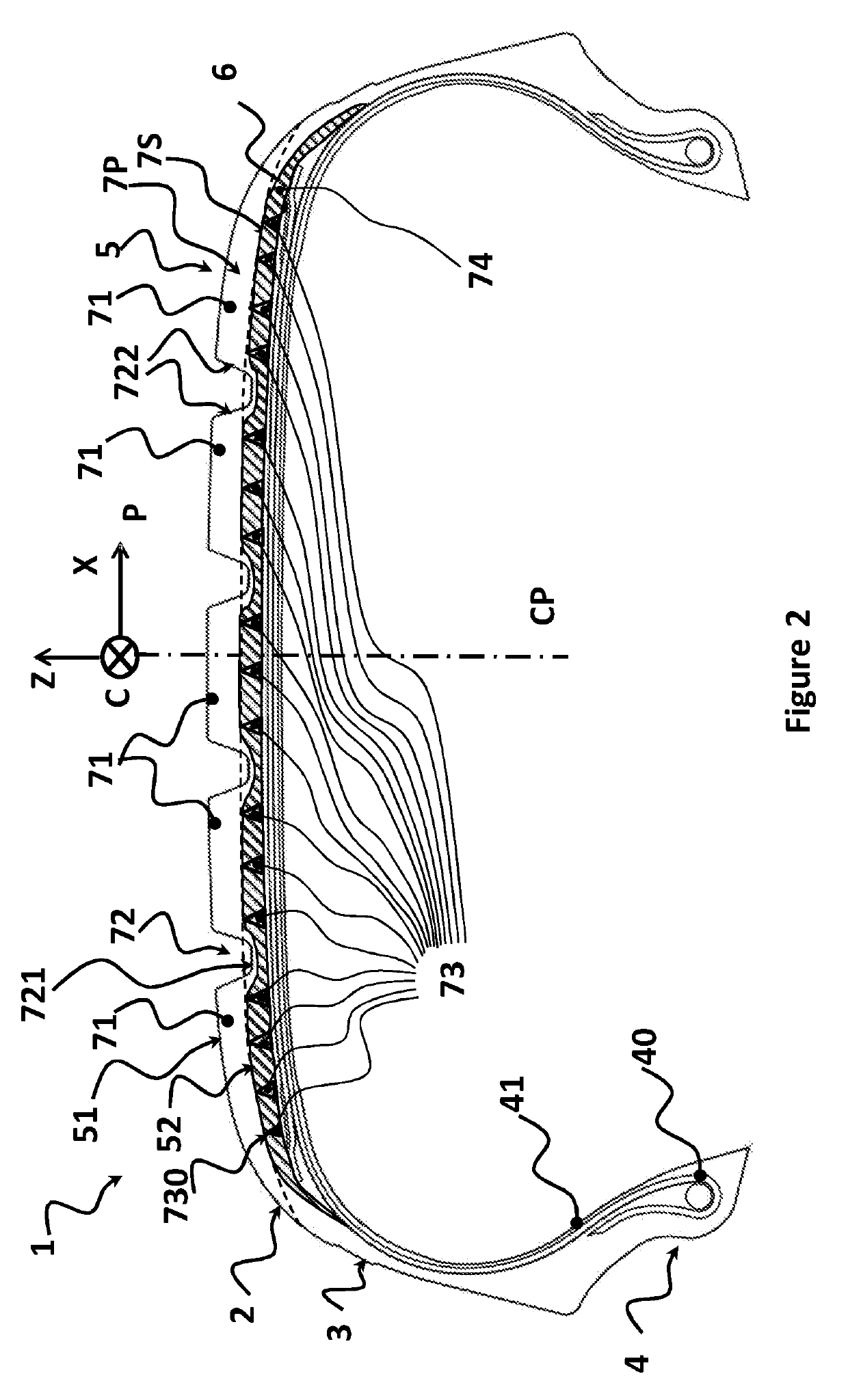
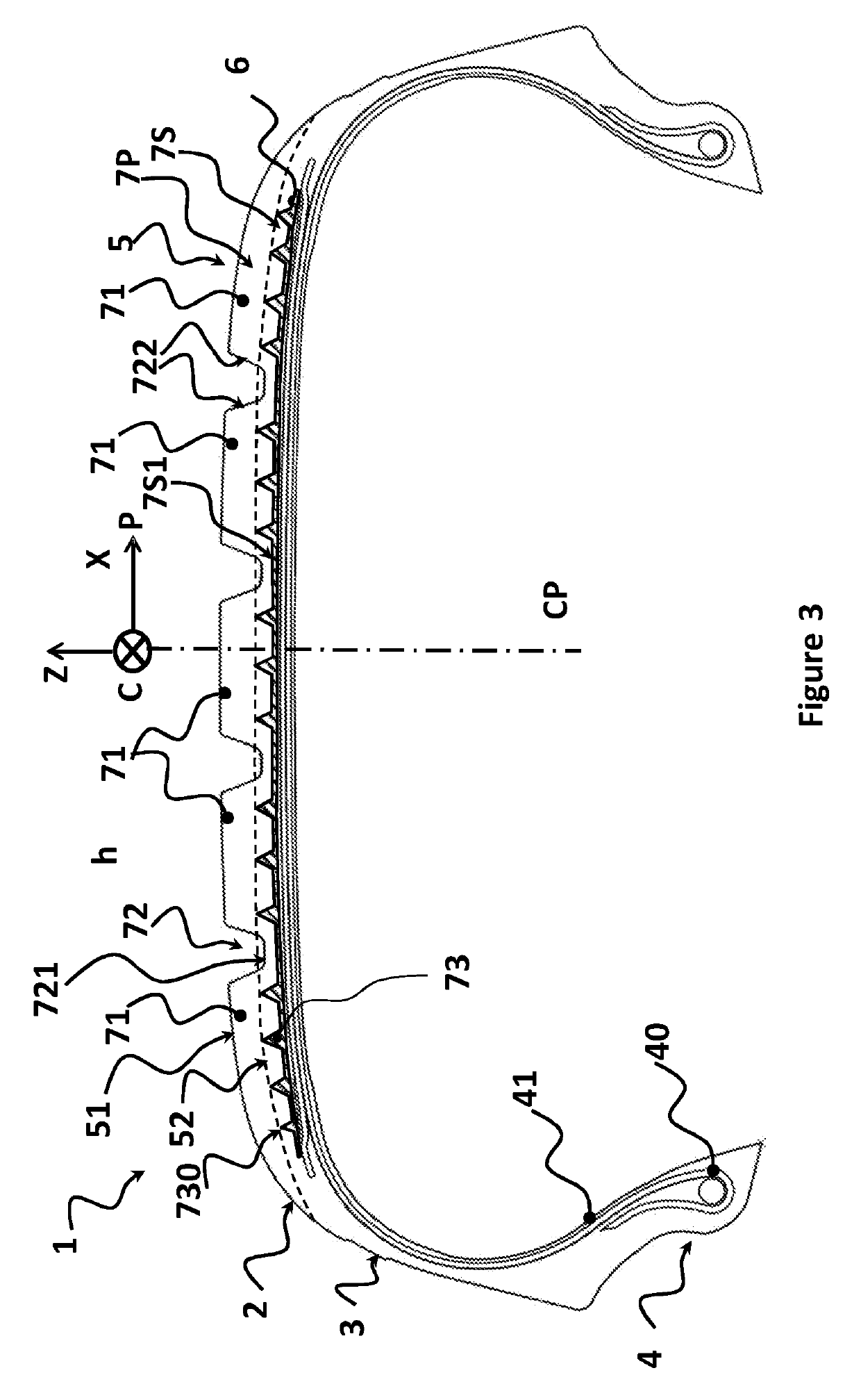
[0033]FIG. 1 shows a tyre 1 comprising a crown 2, two sidewalls 3 each connected to a bead 4. The crown 2 is connected on each side to the radially exterior end of each of the two sidewalls. The crown 2 comprises a tread 5. FIG. 1 indicates an equatorial plane CP, which plane is perpendicular to the axis of rotation of the tyre, situated mid-way between the two beads 4 (mounted on rim) and passing through the middle of the axial width of the crown 2; FIG. 1 also indicates, by arrows placed just above the tread 5, on the equatorial plane CP, the axial X, circumferential C and radial Z directions.

[0034]Each bead has a bead wire 40. A carcass ply 41 is wrapped around each bead wire 40. The carcass ply 41 is radial and is, in a manner known per se, made up of cords; in this implementation, textile cords; these cords are arranged substantially parallel to one another and extending from one bead to the other in such a way that they form an angle of between 80° and 90° with the equatorial ...


PUM


Abstract

A tire (1) comprises two beads (4), two sidewalls (3) connected to the beads and a crown (2) connected to the ends of the two sidewalls, the crown comprising a crown reinforcement (6) and a tread (5) radially outside the crown reinforcement (6), said tread (7) comprising a plurality of tread pattern blocks (71), at least two radially superposed layers: a sublayer (7S) covering the crown reinforcement (6), and a main layer (7P) radially above the crown reinforcement (6), the sublayer comprising a plurality of circumferential reinforcing elements (73) being formed of a rubber compound having greater stiffness than the stiffness of the rubber compound of the rest of the sublayer, the circumferential reinforcing elements (73) extending radially from the radially exterior surface of said crown reinforcement (6) in the direction of the interface between the sublayer (7S) and the main layer (7P), said circumferential reinforcing elements having an axial width which decreases gradually with increasing radial proximity to the outside.

Description

FIELD OF THE INVENTION[0001]The present invention relates to tyres, and more particularly to a tyre the grip performance of which is improved.[0002]In general, a tyre is an object with a geometry exhibiting symmetry of revolution about an axis of rotation. A tyre comprises two beads intended to be mounted on a rim; it also comprises two sidewalls connected to the beads, a crown comprising a tread intended to come into contact with the ground, the crown having a first side connected to the radially outer end of one of the two sidewalls and having a second side connected to the radially outer end of the other of the two sidewalls.[0003]The makeup of the tyre is usually described by a representation of its constituent components in a meridian plane, that is to say a plane containing the axis of rotation of the tyre. The radial, axial and circumferential directions denote the directions perpendicular to the axis of rotation of the tyre, parallel to the axis of rotation of the tyre and p...

Claims


Application Information

Patent Timeline
Patent Type & Authority Applications(United States)
IPC IPC(8): B60C11/00B60C11/18
CPCB60C2011/0033B60C11/18B60C2011/0025B60C11/0075B60C2011/0016B60C11/005
Inventor PERRIN, FRÉDÉRIC
Owner MICHELIN & CO CIE GEN DES ESTAB MICHELIN
Why Eureka
Try Eureka