
Array coil and magnetic resonance imaging apparatus

a magnetic resonance imaging and array coil technology, applied in the field of magnetic resonance imaging apparatus, can solve the problems of difficult to adjust the frequency of an array coil, inability to say that a decrease in weight or flexibility is satisfactory, and difficulty in reducing the weight of the array coil unit, etc., to achieve easy frequency adjustment, small weight, and high flexibility

Inactive Publication Date: 2019-10-10
HITACHI LTD
View PDF3 Cites 3 Cited by
  • Summary
  • Abstract
  • Description
  • Claims
  • Application Information

AI Technical Summary

Benefits of technology

The invention aims to provide an array coil that is flexible, lightweight, and easy to adjust the frequency. This makes it suitable for use in various applications where flexibility and lightweight are important.

Problems solved by technology

Since the number of electronic components mounted therein with an increase in the number of channels increases, the number of hardcovers further increases and thus a decrease in weight of the coil unit is difficult.
However, in the RF coil disclosed in Japanese Patent No. 4820022, since a frequency adjusting circuit is required, the frequency adjusting circuit needs to be covered by a cover and thus it cannot be said that a decrease in weight or improvement in flexibility is satisfactory.
Accordingly, it may be difficult to adjust the frequency of an RF coil with an arbitrary size in the RF coil disclosed in Japanese Patent No. 4820022.

Method used


Image

  • Array coil and magnetic resonance imaging apparatus
  • Array coil and magnetic resonance imaging apparatus
  • Array coil and magnetic resonance imaging apparatus

Examples


modified example

[0103]A modified example of the above-mentioned embodiment will be described below with reference to FIGS. 12A and 12B.

[0104]In the above-mentioned embodiment, the coil unit 500 is formed in a ring shape in which the open ends of the first coil element 501A and the second coil element 501B are adjacent to each other in an area other than the signal detecting unit 502 by inserting the signal detecting unit 502 between the first coil element 501A and the second coil element 501B having the same length and curving the open ends of the first coil element 501A and the second coil element 501B. That is, the signal detecting unit 502 is located at the center of the coil elements 501.

[0105]On the other hand, in this modified example, a ring shape in which a partial area of the first coil element 501A or the second coil element 501B is adjacent to the signal detecting unit 502 is formed by inserting the signal detecting unit 502 between the first coil element 501A and the second coil element...


PUM


Abstract

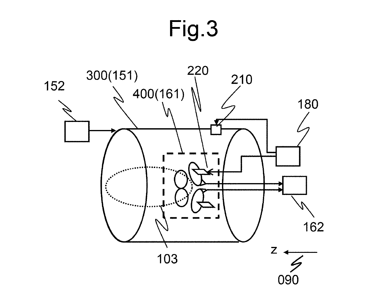
The array-coil includes a plurality of coil units that are each adjusted to receive a magnetic resonance signal from an examinee. Each coil unit includes: a first-coil-element and a second-coil-element of which each is formed of a linear conductor having flexibility with a predetermined length; and a signal detecting unit that is inserted in series between the first-coil-element and the second-coil-element and detects the magnetic resonance signal. One end of each of the first-coil-element and the second-coil-element is connected to the signal detecting unit and the other end thereof is an open end. Adjacent areas are electromagnetically coupled to each other to function by curving and arranging the first-coil-element and the second-coil-element such that at least partial areas on the open end side of the first-coil-element and the open end side of the second-coil-element are adjacent to each other with a predetermined gap therebetween.

Description

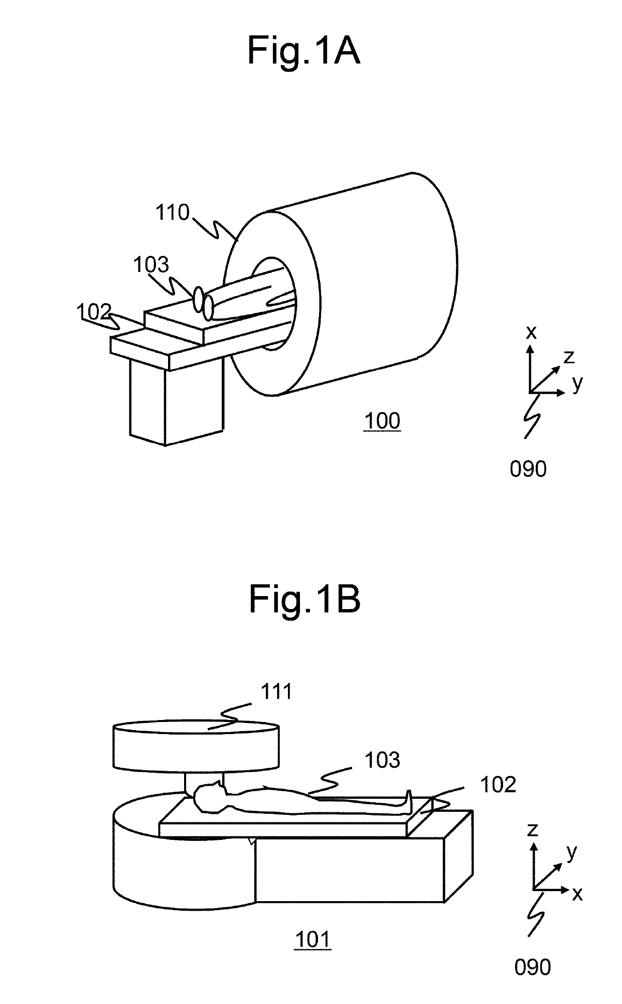
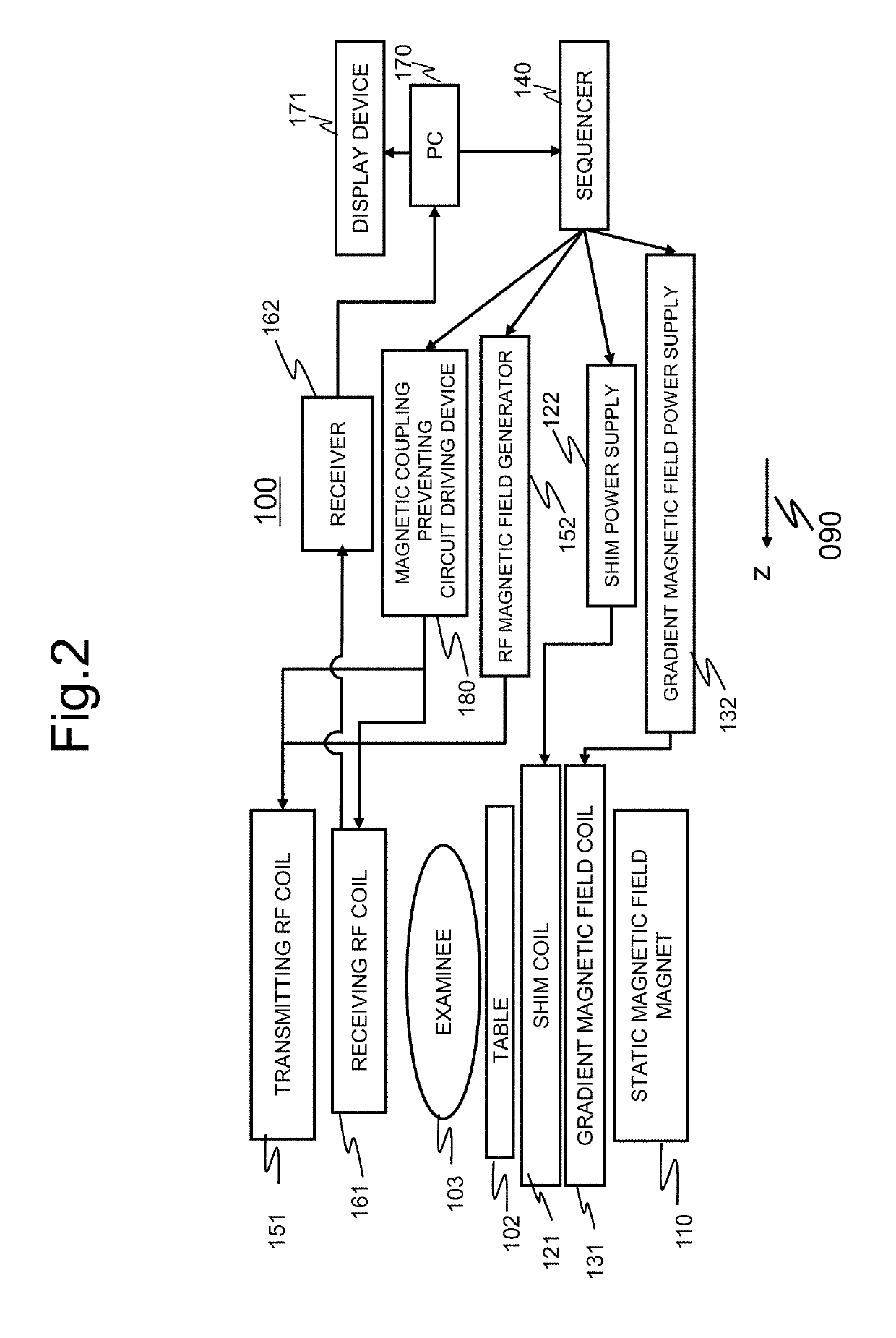
BACKGROUND OF THE INVENTION1. Field of the Invention[0001]The present invention relates to a magnetic resonance imagine (MRI) apparatus and more particularly to a radio-frequency (RF) coil that detects a nuclear magnetic resonance signal by emitting an RF magnetic field.2. Description of the Related Art[0002]An MRI apparatus applies an RF magnetic field to an object placed in a magnetic field (a static magnetic field) which is spatially uniform to generate nuclear magnetic resonance, detects a nuclear magnetic resonance signal which is generated in response thereto, and acquires a tomographic image by performing image processing on the detected signal.[0003]In an MRI apparatus, a device that irradiates an object with an RF magnetic field or detects a nuclear magnetic resonance signal which is generated from the object is referred to as an RF coil. A receiving RF coil that detects a nuclear magnetic resonance signal is adjusted to resonate at the same frequency as the nuclear magneti...

Claims


Application Information

Patent Timeline
IPC IPC(8): G01R33/36G01R33/34
CPCG01R33/3607G01R33/34084G01R33/34046G01R33/34076G01R33/3657G01R33/3415G01R33/34007G01R33/3628
Inventor OTAKE, YOSUKESOTOME, YOSHIHISAOCHI, HISAAKI
Owner HITACHI LTD
Learn More