

Humidifying and cooling apparatus for fuel cell
Active Publication Date: 2019-10-10
HANON SYST
View PDF0 Cites 2 Cited by
- Summary
- Abstract
- Description
- Claims
- Application Information
AI Technical Summary
Benefits of technology
The present invention provides an apparatus for supplying air to a fuel cell with humidification and cooling control. The apparatus includes a water spraying means for cooling and humidifying the air, which can adjust the humidity and lower the temperature of the air simultaneously. A recirculating pipe is provided for collecting unused water and supplying it again to the water spraying means. The water sprayed from the apparatus is sprayed in a direction opposite to the air flow and a hydrophilic evaporation means is further provided for improving the stack output and reliability through an increase in humidification function. Overall, the invention simplifies the apparatus configuration, reduces its size and cost, and improves the performance of the fuel cell.
Problems solved by technology
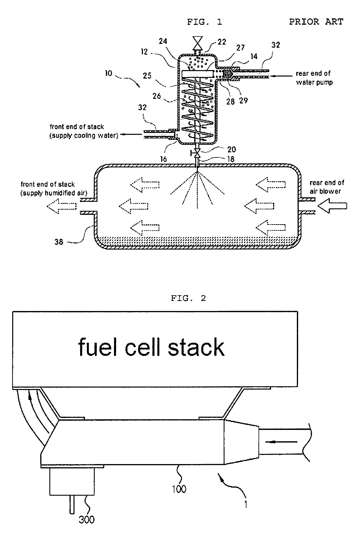
However, since the conventional air supplying system including the air separator for a fuel cell has a large volume of a humidifier and a cooling apparatus, there is a problem in that it is difficult to secure a space when being installed in a vehicle, the degree of freedom in design is lowered, and a flow of air in an engine room is interrupted to adversely affect cooling of other components.
In addition, a membrane type humidifying apparatus has a problem that it is difficult to control a humidification amount and reliability is lowered due to low pressure resistant of the humidifier.
Method used
View moreImage
Smart ImageViewing Examples

Examples
Embodiment Construction
[0082]1: humidifying and cooling apparatus for a fuel cell
[0083]2: air compressor
[0084]3: fuel cell stack
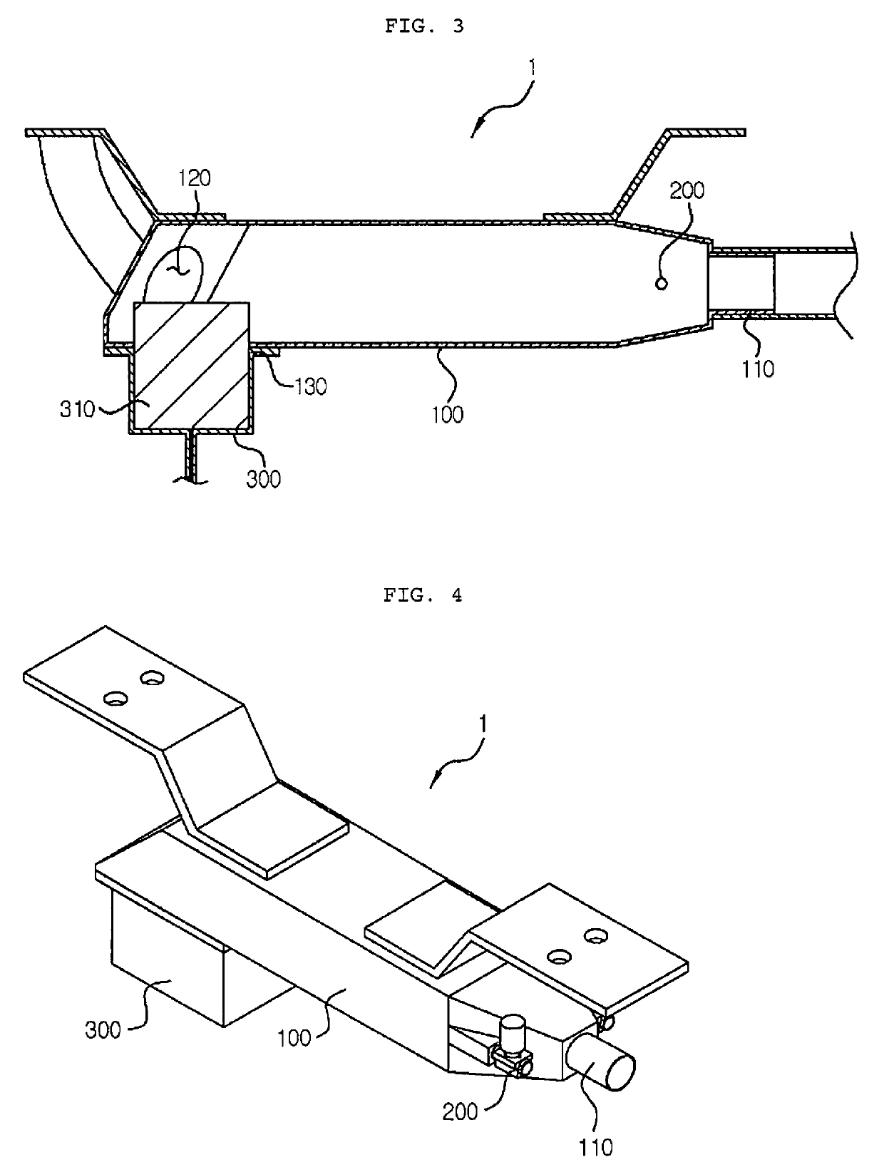
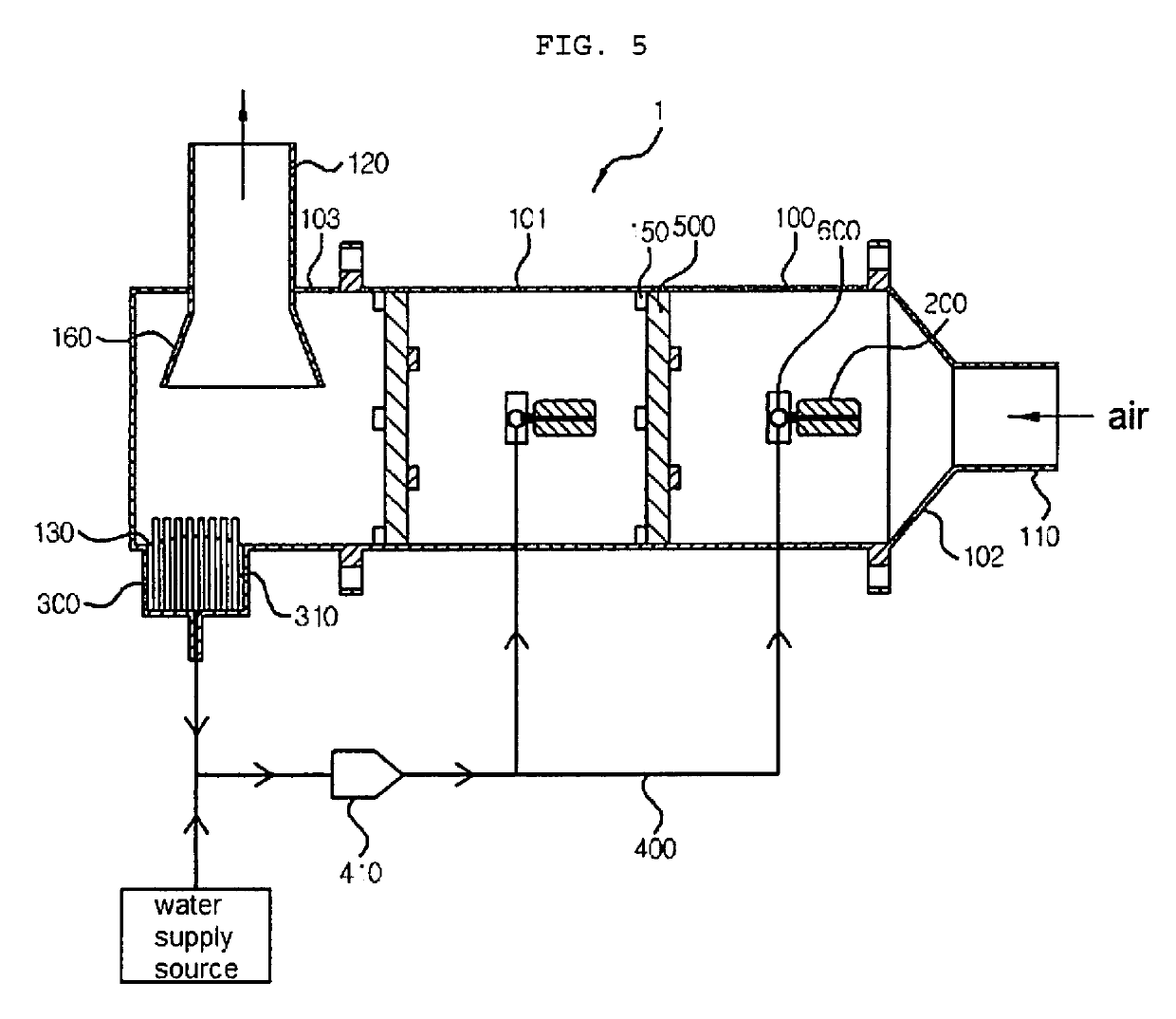
[0085]100: housing
[0086]101: body part
[0087]102: first tank part
[0088]103: second tank part
[0089]110: air inlet
[0090]120: air outlet
[0091]130: drain hole
[0092]140: pipe supporting part
[0093]150: wedge fixing part
[0094]160: outlet pipe
[0095]200: water spraying means
[0096]300: reservoir
[0097]310: evaporation assist means
[0098]400: recycling pipe
[0099]410: water pump
[0100]500: hydrophilic evaporation means
[0101]510: wedge penetration part
[0102]600: water supplying pipe
[0103]700: flange
[0104]710: through hole
[0105]720: sealing means
Login to View More PUM
 Abstract
The present invention relates to a humidifying and cooling apparatus for a fuel cell, and more particularly, to a humidifying and cooling apparatus for a fuel cell for actively and effectively performing a cooling and a humidification control of supplied air, when high-humidity air is supplied to a fuel cell stack in an air supplying apparatus for a fuel cell for supplying an appropriate humidity to the fuel cell stack.
Description
TECHNICAL FIELD[0001]The present invention relates to a humidifying and cooling apparatus for a fuel cell, and more particularly, to a humidifying and cooling apparatus for a fuel cell for actively and effectively performing a cooling and a humidification control of supplied air, when high-humidity air is supplied to a fuel cell stack in an air supplying apparatus for a fuel cell for supplying an appropriate humidity to the fuel cell stack.BACKGROUND ART[0002]A fuel cell system includes a fuel cell stack for generating electric energy, a fuel supplying system for supplying fuel (hydrogen) to the fuel cell stack, an air processing system (APS) for supplying oxygen in the air, which is an oxidizer required for the electrochemical reaction, to the fuel cell stack, a thermal and water management system (TMS) for controlling an operating temperature of the fuel cell stack, and the like.[0003]A basic structure of the fuel cell system has a proton membrane electrode assembly (MEA) in which...
Claims
Login to View More Application Information
Patent Timeline
 IPC IPC(8): H01M8/04119H01M8/0267H01M8/04007H01M8/04492H01M8/04701
CPCH01M8/04731H01M8/04059H01M8/0267H01M8/04126H01M8/04507H01M8/04029H01M8/04201Y02E60/50H01M8/04291H01M8/04089H01M8/04082H01M8/04119Y02P70/50
InventorJANG, KIL SANG
OwnerHANON SYST