Light-emitting apparatus for shooting with flash, charging control method therefor, and storage medium

Inactive Publication Date: 2019-10-10
CANON KK
View PDF4 Cites 2 Cited by
  • Summary
  • Abstract
  • Description
  • Claims
  • Application Information

AI Technical Summary

Benefits of technology

[0014]The present invention provides a light-emitting apparatus and a charging control method therefor which are capable of preventing the perfect moment to take

Problems solved by technology

The charging voltage, however, is required to be at the full charging level when a release switch is operated to prepare for a shooting instruction, thus it wastes power that the charging voltage is maintained at the full charging level even during standby for an operation on the release switch after starting of the camera wastes power.
Particularly when the auto light-emission function is running, the camera automatically judges whether or not to fire a flash, and hence maintaining the charging voltage at the full charging level even during standby for an operation on the rel

Method used


Image

  • Light-emitting apparatus for shooting with flash, charging control  method therefor, and storage medium
  • Light-emitting apparatus for shooting with flash, charging control  method therefor, and storage medium
  • Light-emitting apparatus for shooting with flash, charging control  method therefor, and storage medium

Examples


Example

First Embodiment

(Basic Arrangement of Camera)

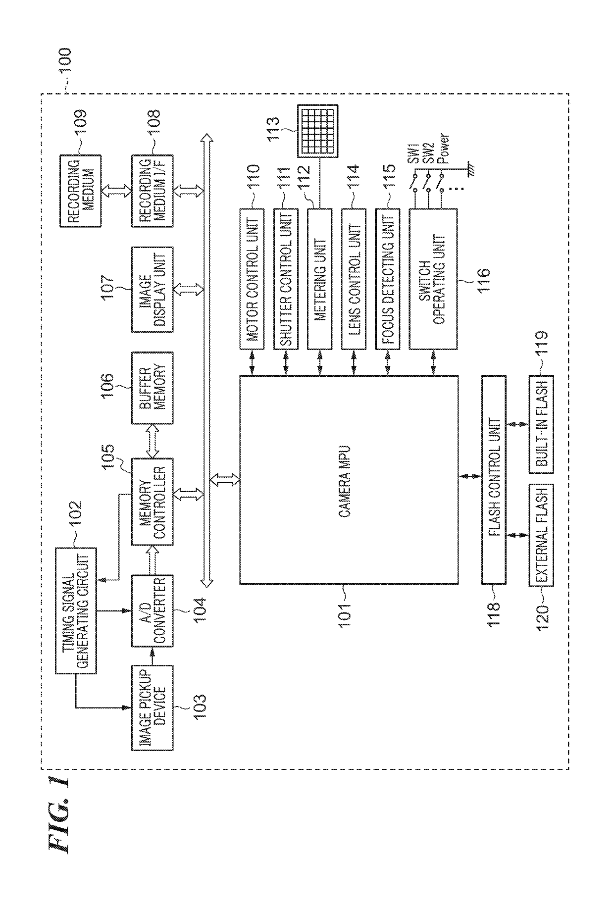
[0030]FIG. 1 is a block diagram showing an arrangement of a digital camera (hereafter simply referred to as “the camera”) 100 on which an external flash 120 which is a light-emitting apparatus according to a first embodiment of the present invention is mounted and which is integrated with a built-in flash 119 which is the light-emitting apparatus.

[0031]It should be noted that one or more of component elements of the camera 100 shown in FIG. 1 may be implemented by hardware such as an ASIC and a programmable logic array (PLA). They may also be implemented by a programmable processor such as a CPU or an MPU executing software.

[0032]They may also be implemented by a combination of software and hardware.

[0033]Therefore, in the following description, even when different component elements are described as operating entities, the same hardware may be implemented as the operating entities.

[0034]The camera 100 has a camera MPU (hereafter simply r...

Example

Second Embodiment

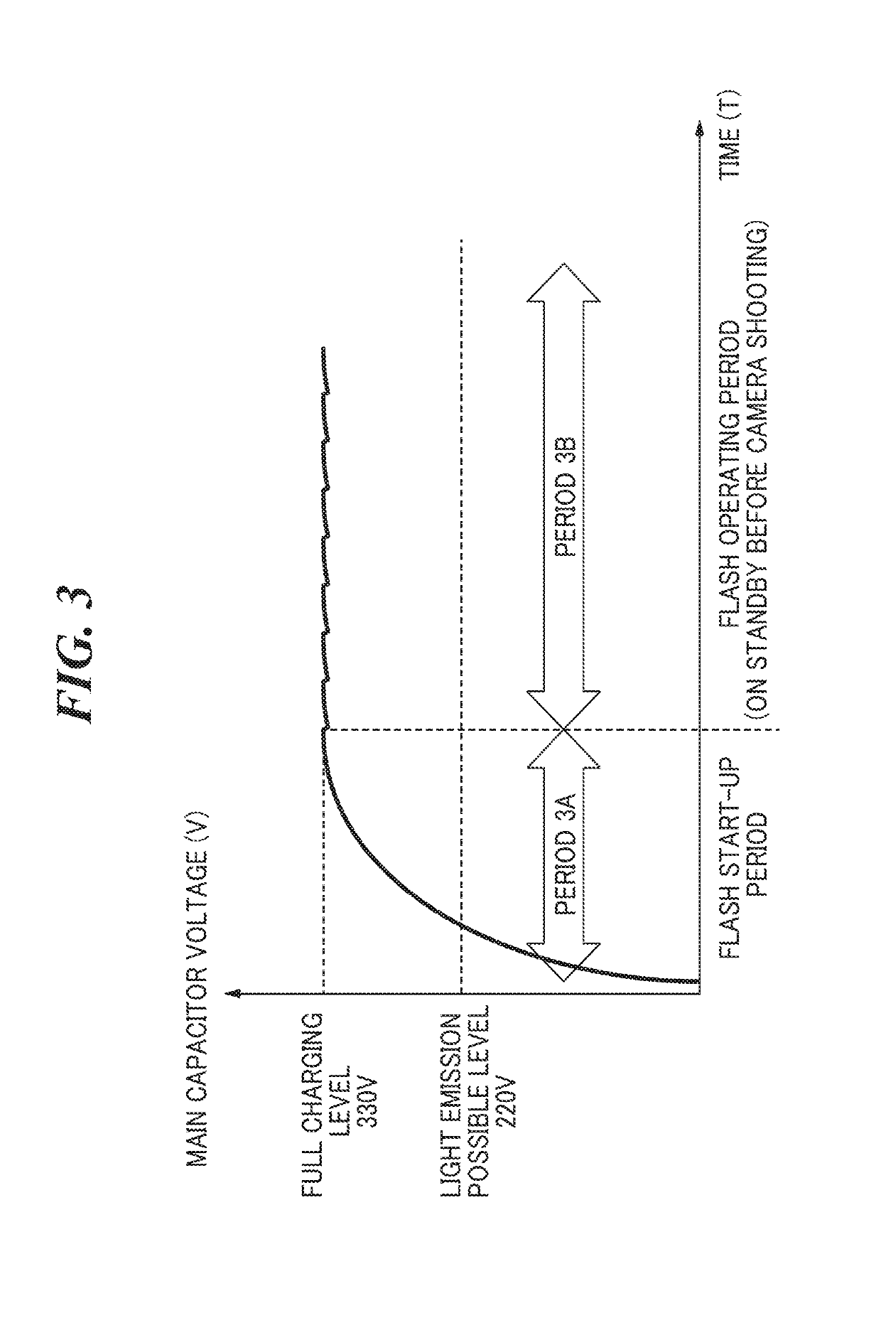
[0090]A second embodiment differs from the first embodiment in that a charging stop level (third level) during a sleep state is provided between the full charging level and the light emission possible level in FIG. 4, and during the sleep state, self discharge is continued until the light emission possible level is reached, and the charging voltage is repeatedly increased until the charging stop level is reached.

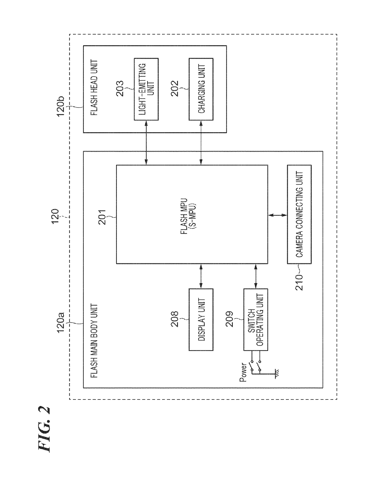
[0091]Thus, the arrangements of the camera 100 and the external flash 120 in FIGS. 1 and 2 are the same as those in the second embodiment and the first embodiment, and hence the same component elements are denoted by the same reference symbols, and duplicate description thereof is omitted.

[0092]First, referring to FIG. 7, a description will be given of charging control (third charging control) for the flash according to the second embodiment.

[0093]Upon receiving a detection signal indicating turning-on of SW1 from the switch operating unit 116, the MPU 101 i...


PUM


Abstract

A light-emitting apparatus which capable of preventing the perfect moment to take a photograph from being missed while reducing draining of a charging unit caused by charging thereof. In accordance with an instruction from a camera 100, a flash MPU of an external flash 120 switches to perform one of a first charging control and a second charging control in accordance with a first instruction from the camera 100. The first charging control charges the charging unit 202 until a charging voltage thereof reaches a target first level and then maintains the charging level at the first level, and the second charging control charges said charging unit 202 until the charging voltage reaches the first level when the charging voltage reaches a second level lower than the first level.

Description

BACKGROUND OF THE INVENTIONField of the Invention[0001]The present invention relates to a light-emitting apparatus, a charging control method therefor, and a storage medium, and in particular to a light-emitting apparatus and a charging control method therefor which are for use in shooting with a flash, as well as a storage medium.Description of the Related Art[0002]Conventionally, a flash has been used for shooting in a dark scene, a back-light scene, and so forth.[0003]A function of causing a camera to automatically judge whether or not to use the flash in shooting is known as an auto light-emission function.[0004]Shooting with the flash is conducted as follows: a capacitor connected to a light-emitting unit of the flash is charged with electric charge to a level at which light emission by the light-emitting unit is possible, and then the light-emitting unit is caused to emit light by feeding the electric charge into the light-emitting unit.[0005]The amount of light emitted by the...

Claims


Application Information

Patent Timeline
IPC IPC(8): H04N5/235G03B15/05H05B33/08H02J7/00H05B44/00
CPCG03B2215/0567H02J7/007H02J7/345H04N5/2354G03B15/05H05B33/0845H04N5/2351H05B41/325H05B45/10H04N23/71H04N23/74
Inventor MATSUMOTO, YUKIHIROTAKAI, JUNJI
Owner CANON KK
Why Eureka
Try Eureka