Digital broadcasting system and digital broadcast transmission and reception method

a digital broadcasting and transmission system technology, applied in the field of digital broadcasting systems, can solve the problems of difficult terminals to receive long-time broadcast services continuously, large power consumption,

Active Publication Date: 2010-03-23
SOVEREIGN PEAK VENTURES LLC
View PDF7 Cites 2 Cited by
  • Summary
  • Abstract
  • Description
  • Claims
  • Application Information

AI Technical Summary

Benefits of technology

[0008]The present invention has been conceived in order to solve the above conventional problems, and an object thereof is to provide a digital broadcasting system or the like which prevents reproduction of a service from being discontinued even in the low C / N condition or the like.
[0010]According to the above structure, the probability that the lower layer code (second layer code) of smaller code size can be obtained is high even if the synchronization of the data burst is lost in the low C / N or the like. Therefore, it becomes possible to decode the lower layer so as to continue the reproduction of the service without being interrupted.
[0012]According to the above structure, even if the synchronization of the data burst is lost in the lower C / N, the clocking unit and the prediction window generating unit open the prediction window at the time when the data burst appears in the broadcast stream, so that the stream can be obtained only while the prediction window opens. Therefore, it becomes possible to prevent the reproduction of the service from being discontinued by the loss of synchronization.
[0014]According to the above structure, even if the synchronization of the data burst is lost in the lower C / N, the power supply is controlled so that the data burst is received only while the prediction window opens. Therefore, it becomes possible to reduce the power consumption even during the recovery of synchronization, and to reduce the drain of the battery that is the power source.
[0023]According to the present invention, in the case where the synchronization of the data burst is lost in the low C / N or the like, the clocking unit predicts the time at which the data burst appears in the stream and opens the prediction window. Therefore, it becomes possible to obtain the stream only while the prediction window opens. In addition, even in the case where the position of the prediction window deviates from the actual position of the data burst, it becomes possible to decode the lower layer code (second layer code) of small code size so as to prevent the reproduction of the service from being discontinued.

Problems solved by technology

Unlike the Japanese standard, the European standard does not define this partial reception of the frequency segments, so it is necessary to receive all the frequency bands of the broadcast wave in series in order to receive the broadcast service at the mobile terminal, which results in the consumption of much power particularly in the high frequency front end module.
Therefore, in a mobile terminal driven by a battery, the battery is drained so quickly that it becomes difficult for the terminal to receive a long-time broadcast service continuously.
This is a practical problem.
However, the above time-slicing scheme has the following problems.
In addition, since the tuning / demodulation unit needs to be powered on continuously for the recovery of synchronization, much power is consumed.

Method used


Image

  • Digital broadcasting system and digital broadcast transmission and reception method
  • Digital broadcasting system and digital broadcast transmission and reception method
  • Digital broadcasting system and digital broadcast transmission and reception method

Examples


first embodiment

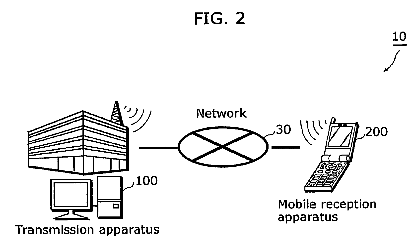
[0048]FIG. 2 is a schematic diagram of a digital broadcasting system 10 according to the present embodiment. As shown in FIG. 2, the digital broadcasting system 10 includes a transmission apparatus 100 and at least one mobile reception apparatus 200, and these apparatuses are connected with each other via a network 30.

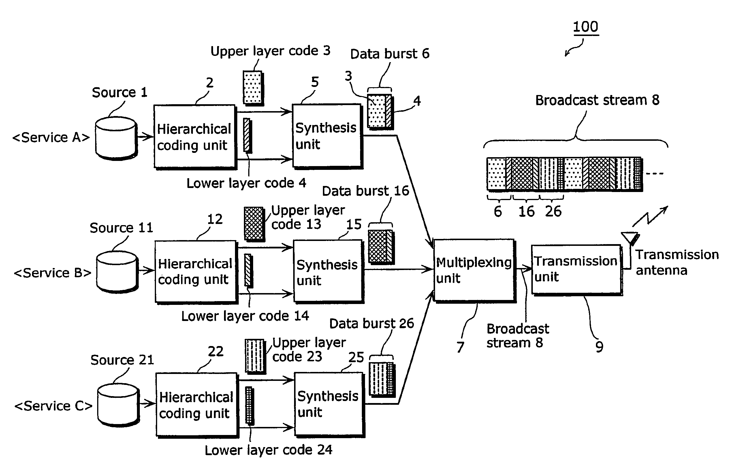
[0049]The transmission apparatus 100 generates a broadcast stream by multiplexing sources (which are also referred to as contents) for supplying various services to a user (which is also referred to as a viewer), and transmits the broadcast stream to the network 30.

[0050]The mobile reception apparatus 200 is a mobile phone including, for example, a digital broadcast tuner, a liquid crystal panel and a speaker. This mobile reception apparatus 200 receives a broadcast stream via the network 30, decodes it, and displays the contents of the service selected by the user on the liquid crystal panel or the like.

[0051]FIG. 3 is a block diagram showing schematically the functio...

second embodiment

[0115]The above description is given of the first embodiment in which the window width of the prediction window signal S3 is fixed. A description is given below of the second embodiment in which the window width of the prediction window signal S3 is gradually expanded if the reception condition is not improved.

[0116]FIG. 12 is a block diagram showing the functional structure of the burst prediction unit 315 in the present embodiment.

[0117]Note that in FIG. 12, the same reference numbers are assigned to the same components shown in FIG. 8 of the first embodiment, and the description thereof. Is not repeated here.

[0118]As shown in FIG. 12, the pulse generator 901 can set from outside the prediction window width of the prediction window signal S3, namely, the value of the pulse width. The counter 903 counts the number of pulses of the count clock S4, and outputs the count value into the pulse width register 902. The pulse width register 902 calculates the pulse width value based on the...

third embodiment

[0125]FIG. 15 is a block diagram showing the functional structure of a mobile reception apparatus 1100 according to the present embodiment of the present invention. In FIG. 15, the same reference numbers are assigned to the same components shown in FIG. 4 of the first embodiment, and the description thereof is not repeated here.

[0126]In FIG. 15, the mobile reception apparatus 1100 includes a VCO unit 1101 and a phase comparison unit 1102.

[0127]The VCO unit 1101 is a voltage control oscillator which changes the oscillatory frequency by controlling the voltage according to an inputted VCO control signal, and generates a count clock S4.

[0128]The phase comparison unit 1102 compares the phases of the burst synchronization signal S1 and the count clock S4, converts the phase difference into a voltage value, and outputs it as a VCO control signal. When the phases are compared, the loop gain of the count clock S4 is adjusted by the ΔT information S2, and therefore the accuracy of phase comp...


PUM


Abstract

A digital broadcasting system transmitting and receiving a broadcast stream created from a broadcast source. The system includes a hierarchical coding unit (2) coding the broadcast source depending on a characteristic of the broadcast source and generating, from the coded broadcast source, a first layer code and a second layer code which can respectively be used for reproduction of the broadcast source and includes a synthesis unit (5) generating data bursts, each including the generated first and second layer code. The system also includes a multiplexing unit (7) creating the broadcast stream by multiplexing the generated data bursts, a transmission unit (9) transmitting the created broadcast stream to the network, a tuning / demodulation unit (301) receiving the transmitted broadcast stream, a synchronization unit (302) extracting, from the received broadcast stream, at least one of the first layer code and the second layer codes and a TS decoder (303) reproducing the broadcast source using the extracted code.

Description

BACKGROUND OF THE INVENTION[0001]1. Field of Invention[0002]The present invention relates to a digital broadcasting system, and particularly to a method of transmitting and receiving digital broadcasts and digital data broadcasts suitable for mobile terminals driven by batteries and a transmission apparatus and a reception apparatus in the digital broadcasting system.[0003]2. Description of the Related Art[0004]In Europe, digital terrestrial broadcasts are transmitted to stationary receiving terminals according to the standard (DVB-T EN 300 477) developed by the European Technical Standards Institute (ETSI). In order to receive a digital terrestrial broadcast at a mobile terminal, a broadcast wave is divided into frequency segments in advance and then transmitted, as defined in a Japanese domestic standard (ARIB STD-B31). In this case, a popular television receiver receives all the segments to reproduce them on a large-sized screen, while a mobile terminal receives only one or a few...

Claims


Application Information

Patent Timeline
Patent Type & Authority Patents(United States)
IPC IPC(8): G11C29/00H04N19/102H04H20/42H04H60/11H04N7/24H04N19/134H04N19/187H04N19/189H04N19/30H04N19/65H04N19/70H04N21/2343H04N21/462H04N21/63H04N21/643
CPCH04H20/42H04H60/11H04N21/234327H04N21/4621H04N21/631H04N21/64315H04H20/426
Inventor MIZUTA, TAKASHI
Owner SOVEREIGN PEAK VENTURES LLC
Why Eureka
Try Eureka