
Method and System for Detecting Volatile Organic Compounds within a Battery Assembly

a battery and volatile organic technology, applied in secondary cell servicing/maintenance, batteries, instruments, etc., can solve the problems of li-ion batteries, notable failures in lithium-ion chemistry, damage and death, etc., and achieve the effect of minimizing the hazard

Inactive Publication Date: 2019-10-17
ASTRONICS ADVANCED ELECTRONICS SYST
View PDF2 Cites 6 Cited by
  • Summary
  • Abstract
  • Description
  • Claims
  • Application Information

AI Technical Summary

Benefits of technology

The patent is about a system and method to prevent a rechargeable battery from exploding due to the gas released by a failing battery cell. This is done by using a sensor that detects a specific gas produced by the battery cell. This sensor can be integrated into existing battery designs to provide an extra layer of protection and reduce the risks associated with battery failure.

Problems solved by technology

Unexpected battery failures may lead to inconvenient and even dangerous circumstances, particularly when employed in enclosed environments or where flammable materials are in proximity.
Particularly, batteries employing lithium-ion (Li-ion) chemistry have had notable failures causing damage and fatalities.
These can be particularly dangerous in aircraft when a failure occurs in overhead stowage bins or luggage storage areas, which has led to a ban on Li-ion batteries in checked baggage.
Li-ion battery failures may occur regardless of power density capacity, physical size or the types of personal, commercial or industrial applications in which they are employed.
Even with existing industrial design standards and various regimes of government regulations concerning appropriate construction, manufacturing and safe operation of various battery chemistries, such as Li-ion battery technologies, failures of such batteries continue to occur.
Liquid organic electrolytes have high volatility and flammability, and elevated voltages and / or temperatures result with the electrolytes reacting with the active battery materials to release heat and gaseous by products.
The third phase is where chemicals in the battery ignite, causing a catastrophic failure.

Method used


Image

  • Method and System for Detecting Volatile Organic Compounds within a Battery Assembly
  • Method and System for Detecting Volatile Organic Compounds within a Battery Assembly
  • Method and System for Detecting Volatile Organic Compounds within a Battery Assembly

Examples


Embodiment Construction

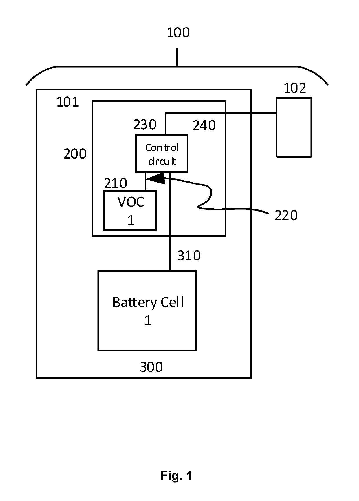
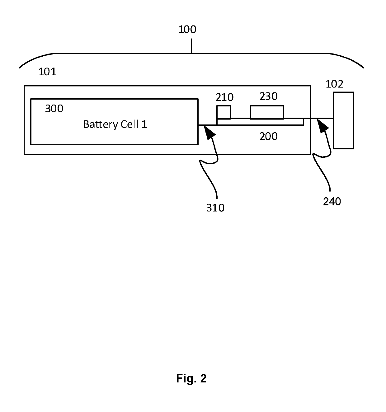
[0017]With reference to FIGS. 1-2, an embodiment incorporates a VOC sensor 210 into any existing rechargeable battery system design providing an additional protection method to minimize the hazard associated with various battery failure mechanisms, resulting in the outgassing of harmful chemicals.

[0018]VOC sensors 210 may be a Total VOC sensor (TVOC), which is a non-selective device that detects a wide variety of VOCs. In an embodiment, the TVOC may have a typical measurement level between 0 and 2000 ppm. The VOC sensor 210 may also be a targeted VOC sensor, which includes a specific correction factor used for sensor calibration. That is, a targeted VOC sensor may be used for a specific chemical, or for a subset of chemicals, and may be calibrated to detect for those particular VOC chemicals. A threshold value is configured for VOC concentration levels. For example, in a three-cell 60 Wh battery assembly, a threshold level may be set to 90 or 100 ppb (parts per billion).

[0019]A batt...


PUM

PropertyMeasurementUnit
pressureaaaaaaaaaa
boiling pointaaaaaaaaaa
threshold levelaaaaaaaaaa

Abstract

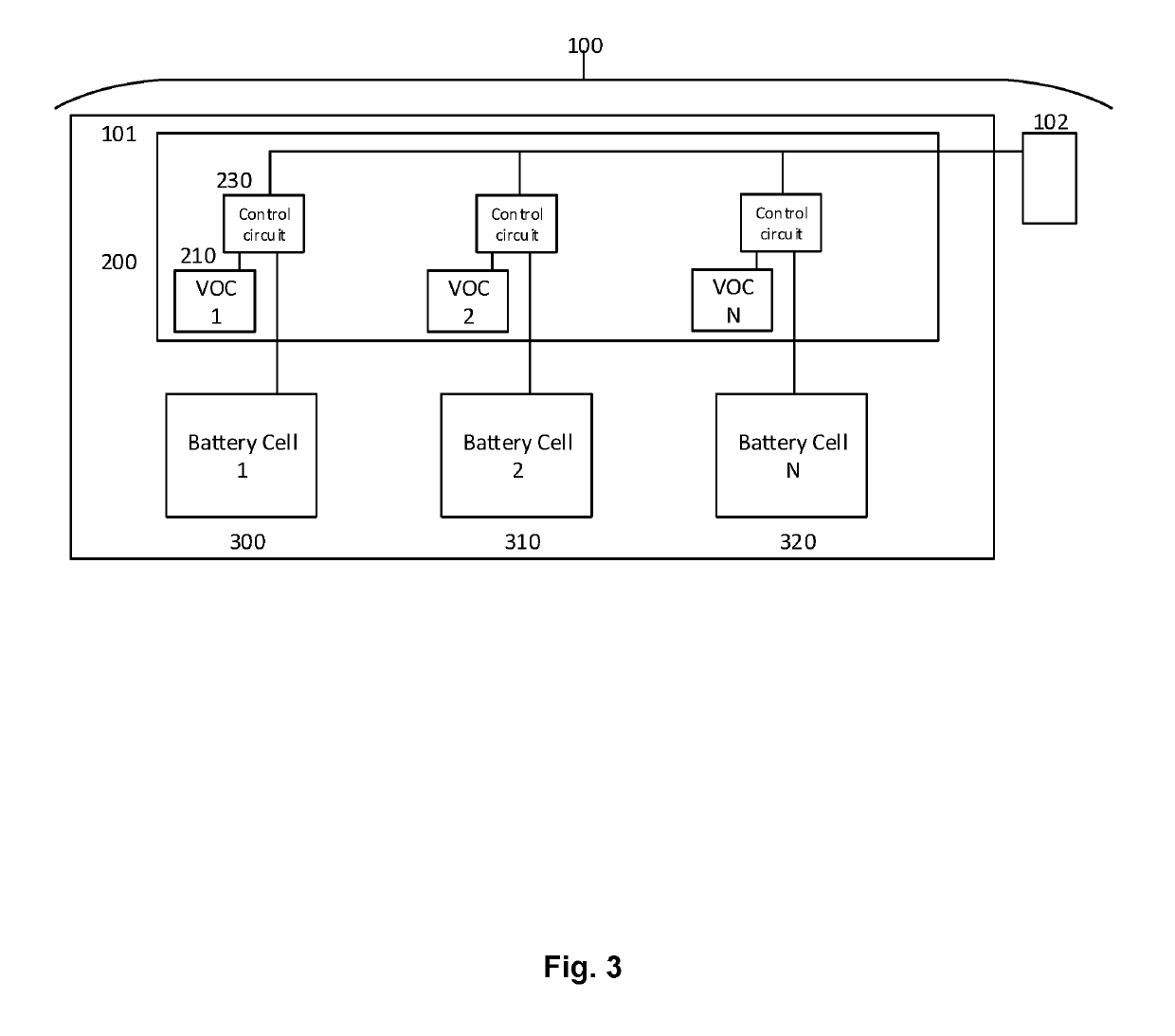
Disclosed is a battery system having a battery package assembly including a battery cell and a battery control circuit, wherein the battery control circuit includes an internal volatile organic compound (VOC) sensor and a control circuit. The battery cell is connected to the battery control circuit, which is in turn connected to an external interface connection. The VOC sensor is configured to detect the presence of a VOC within the battery package assembly indicating a failure or impending failure the battery cell.

Description

FIELD OF THE DISCLOSURE[0001]The subject matter of the present disclosure generally relates to monitoring battery assemblies' gaseous discharges, and more particularly relates to detecting volatile organic compounds (VOCs) within battery assemblies.BACKGROUND OF THE DISCLOSURE[0002]Unexpected battery failures may lead to inconvenient and even dangerous circumstances, particularly when employed in enclosed environments or where flammable materials are in proximity.[0003]Particularly, batteries employing lithium-ion (Li-ion) chemistry have had notable failures causing damage and fatalities. These can be particularly dangerous in aircraft when a failure occurs in overhead stowage bins or luggage storage areas, which has led to a ban on Li-ion batteries in checked baggage. These batteries are also however the most widely utilized battery type in portable electronic devices around the world. Li-ion battery failures may occur regardless of power density capacity, physical size or the type...

Claims


Application Information

Patent Timeline
Patent Type & Authority Applications(United States)
IPC IPC(8): H01M10/48G01N33/00H01M10/42
CPCH01M2010/4271H01M10/488H01M10/482H01M2010/4278H01M10/425G01N33/0047H01M10/48H01M10/0525H01M2200/00Y02E60/10
Inventor FIFIELD, JON
Owner ASTRONICS ADVANCED ELECTRONICS SYST
Learn More