Waveguides with active or passive repeaters for range extension
What is AI technical title?
AI technical title is built by Patsnap AI team. It summarizes the technical point description of the patent document.
a repeater and waveguide technology, applied in waveguides, high-frequency circuit adaptations, printed circuit non-printed electric components association, etc., can solve the problems of increasing the cost of traditional electrical connections, increasing power consumption, and requiring additional power
Active Publication Date: 2019-10-17
INTEL CORP
View PDF0 Cites 4 Cited by
Summary
Abstract
Description
Claims
Application Information
AI Technical Summary
This helps you quickly interpret patents by identifying the three key elements:
Problems solved by technology
Method used
Benefits of technology
Benefits of technology
The patent text describes a technology for improving interconnects in server architectures. The technology involves the use of mm-wave waveguides with active or passive repeaters to extend the range of the waveguides and provide higher data rates. The invention aims to address the need for faster and more cost-effective interconnects in emerging rack-scale architectures. The technical effects of the invention include higher data rates, lower power consumption, and minimized latency.
Problems solved by technology
However, as new architectures emerge, such as 100 GigabitEthernet, traditional electrical connections are becoming increasingly expensive and power hungry to support the required data rates for short (e.g., 2 meters to 5 meters) interconnects.
Accordingly, these solutions require additional power and increase the latency to the system.
Optical transmission over fiber is capable of supporting the required data rates and distances, but at a severe power and cost penalty, especially for short to medium distances (e.g., a few meters) due to the need for optical interconnects.
For some distances and data rates required in proposed architectures, there is no viable electrical solution today.
For medium distance communication in a server farm, the overhead power associated with the optical fiber interconnects is too high, whereas the required error correction on traditional electrical cables creates a substantial latency (e.g., several hundred nanoseconds).
This makes both technologies (traditional electrical and optical) not particularly optimal for emerging rack-scale architectures (RSA) servers including HPCs, where many transmission lines range between 2 and 5 meters.
However, the propagation of mm-waves along a dielectric cable may be loss-limited if the incurred dispersion over the length of the channel is not significant (typically in pure dielectric waveguides), or may be dispersion limited if the incurred dispersion over the length of the channel is significant (typically in metalair core waveguides).
Accordingly, in longer mm-wave waveguides the signal may incur excessive dispersion and spread too much, therefore becoming difficult to decode at the receiving end.
Method used
Image
Click on the blue label to locate the original text in one second.
Reading with bidirectional positioning of images and text.
Examples
example 3
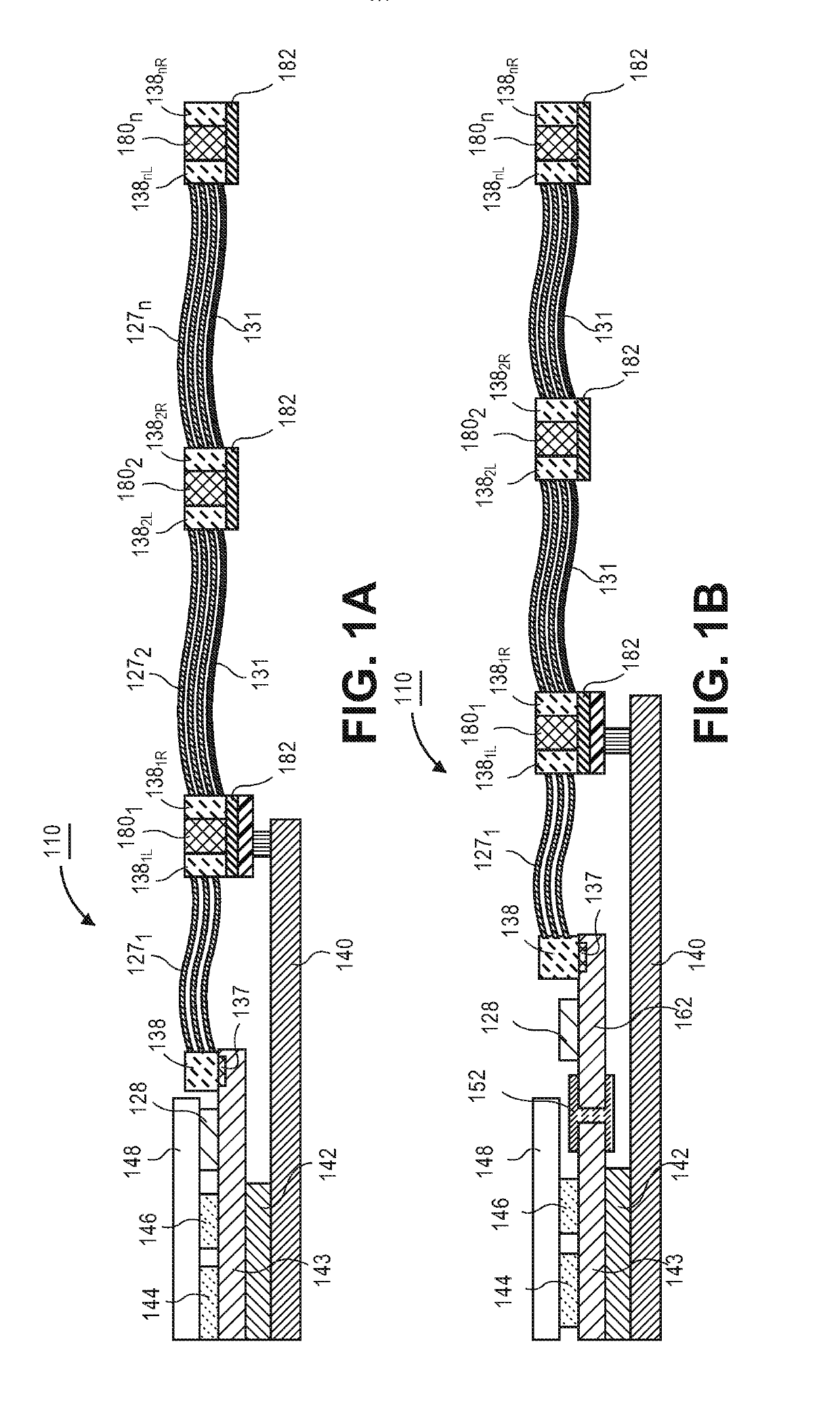
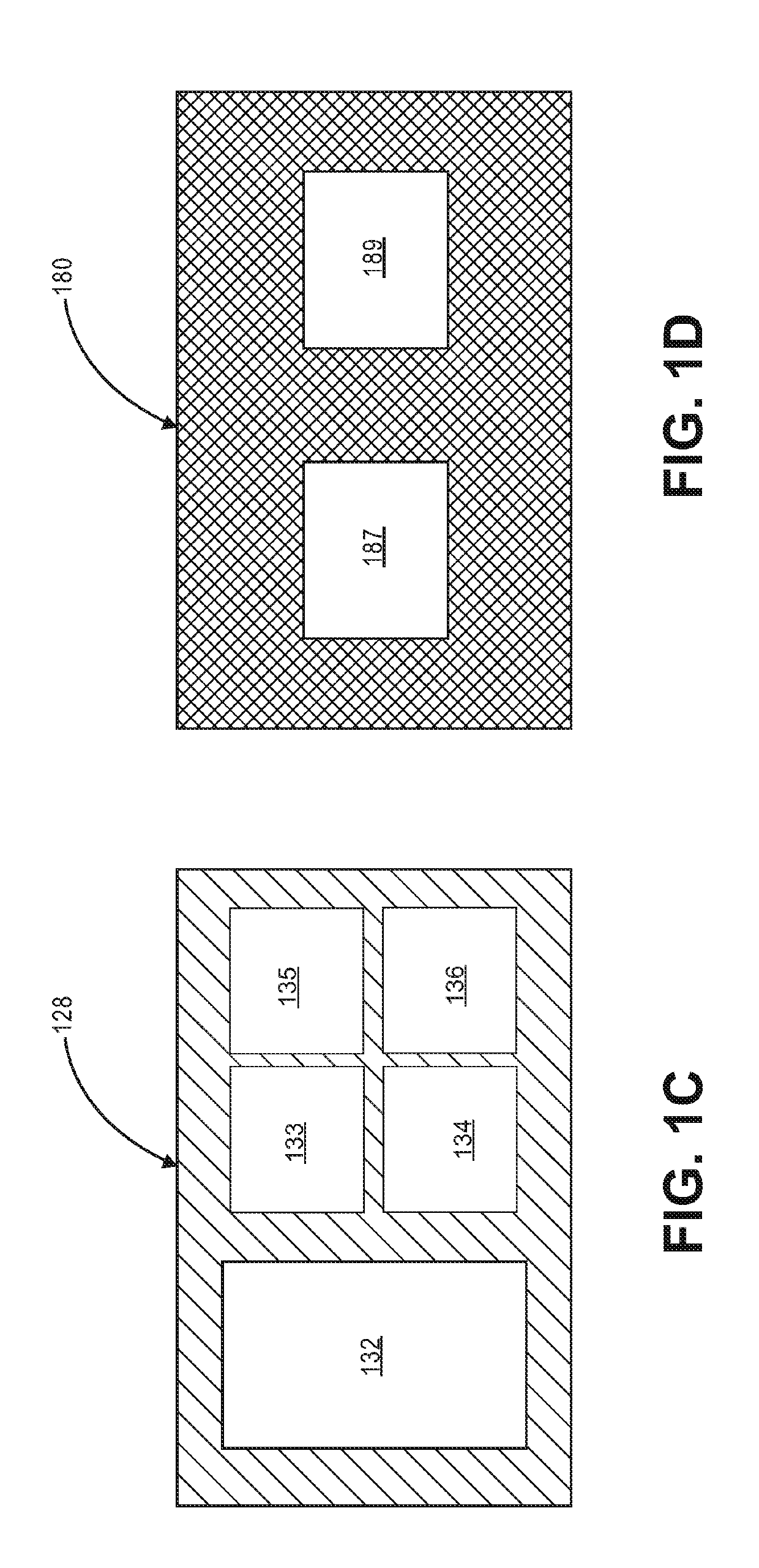
[0058] the mm-wave waveguide of Example 2, wherein the active repeater includes one or more semiconducting dies packaged on a repeater substrate.
example 4
[0059] the mm-wave waveguide of Example 3, wherein the first dielectric waveguide is communicatively coupled to the repeater with a first mm-wave waveguide connector formed on the repeater substrate, and wherein the second dielectric waveguide is communicatively coupled to the repeater by a second mm-wave waveguide connector formed on the repeater substrate.
example 5
[0060] the mm-wave waveguide of Example 3 or Example 4, wherein the one or more semiconducting dies include an analog filter.
[0061]Example 6: the mm-wave waveguide of Example 5, wherein the analog filter is an RF analog filter.
[0062]Example 7: the mm-wave waveguide of Example 5 or Example 6, wherein the one or more semiconducting dies further includes an RF amplifier.
[0063]Example 8: the mm-wave waveguide of Example 7, wherein the RF analog filter and the RF amplifier are formed on a single die.
[0064]Example 9: the mm-wave waveguide of Example 2, Example 3, Example 4, Example 5, Example 6, Example 7, or Example 8, further comprising: a power supply line electrically coupled to the repeater.
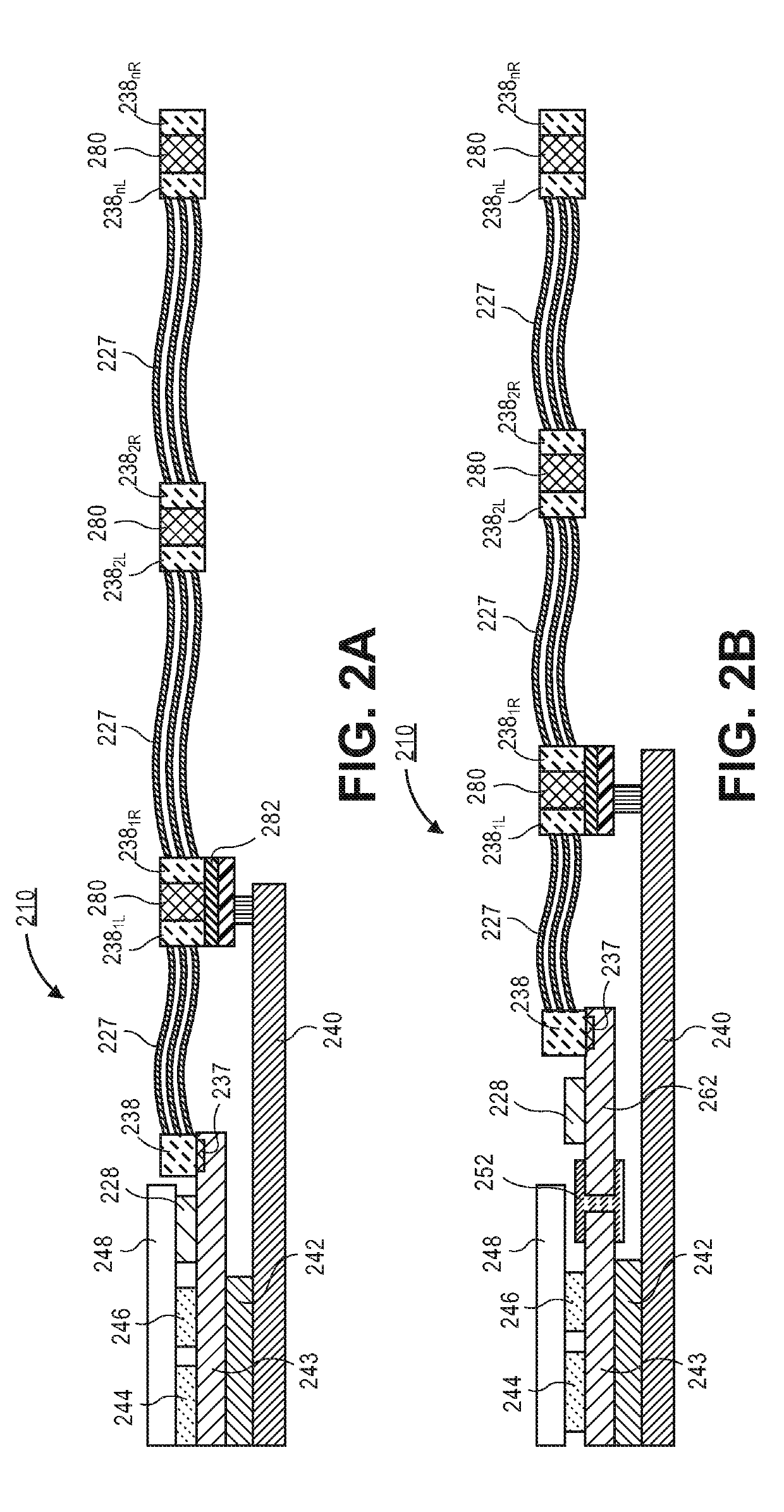
[0065]Example 10: the mm-wave waveguide of Example 1, wherein the repeater is a passive repeater.
[0066]Example 11: the mm-wave waveguide of Example 10, wherein the repeater includes one or more transmission lines formed on a substrate.
[0067]Example 12: the mm-wave waveguide of Example 11, wherein ...
PUM
Abstract
Embodiments of the invention may include a mm-wave waveguide. In an embodiment, the mm-wave waveguide may include a first dielectricwaveguide and a second dielectric waveguide. A conductive layer may be used to cover the first dielectric waveguide and the second dielectric waveguide in some embodiments. Furthermore, embodiments may include a repeater communicatively coupled between the first dielectric waveguide and the second dielectric waveguide. In an embodiment, the repeater may be an active repeater or a passive repeater. According to an embodiment, a passive repeater may be integrated within the dielectric waveguide. The passive repeater may include a dispersion compensating material that produces a dispersion response in a signal that is substantially opposite to a dispersion response produced when the signal is propagated along the dielectric waveguide.
Description
FIELD OF THE INVENTION[0001]Embodiments of the invention are in the field of interconnect technologies and, in particular, formation of mm-wave waveguides that include active or passive repeaters that extend the range of the mm-wave waveguides.BACKGROUND OF THE INVENTION[0002]As more devices become interconnected and users consume more data, the demand on improving the performance of servers has grown at an incredible rate. One particular area where server performance may be increased is the performance of interconnects between components, because there are many interconnects within server and high performance computing (HPC) architectures today. These interconnects include within blade interconnects, within rack interconnects, and rack-to-rack or rack-to-switch interconnects. In order to provide the desired performance, these interconnects may need to have increased data rates and switching architectures which require longer interconnects. Furthermore, due to the large number of in...
Claims
Application Information
Patent Timeline
Application Date:The date an application was filed.
Publication Date:The date a patent or application was officially published.
First Publication Date:The earliest publication date of a patent with the same application number.
Issue Date:Publication date of the patent grant document.
PCT Entry Date:The Entry date of PCT National Phase.
Estimated Expiry Date:The statutory expiry date of a patent right according to the Patent Law, and it is the longest term of protection that the patent right can achieve without the termination of the patent right due to other reasons(Term extension factor has been taken into account ).
Invalid Date:Actual expiry date is based on effective date or publication date of legal transaction data of invalid patent.

