Motor, compressor, refrigerating and air conditioning apparatus, and method for manufacturing motor
a technology for compressors and motors, applied in the field of motors, compressors, refrigerating and air conditioning equipment, and manufacturing methods, can solve the problems of iron loss and motor efficiency decline, and achieve the effects of reducing the size of the motor, improving motor efficiency, and suppressing the magnetic flux from the stator into the shell
- Summary
- Abstract
- Description
- Claims
- Application Information
AI Technical Summary
Benefits of technology
Problems solved by technology
Method used
Image
Examples
first embodiment
(Configuration of Motor)
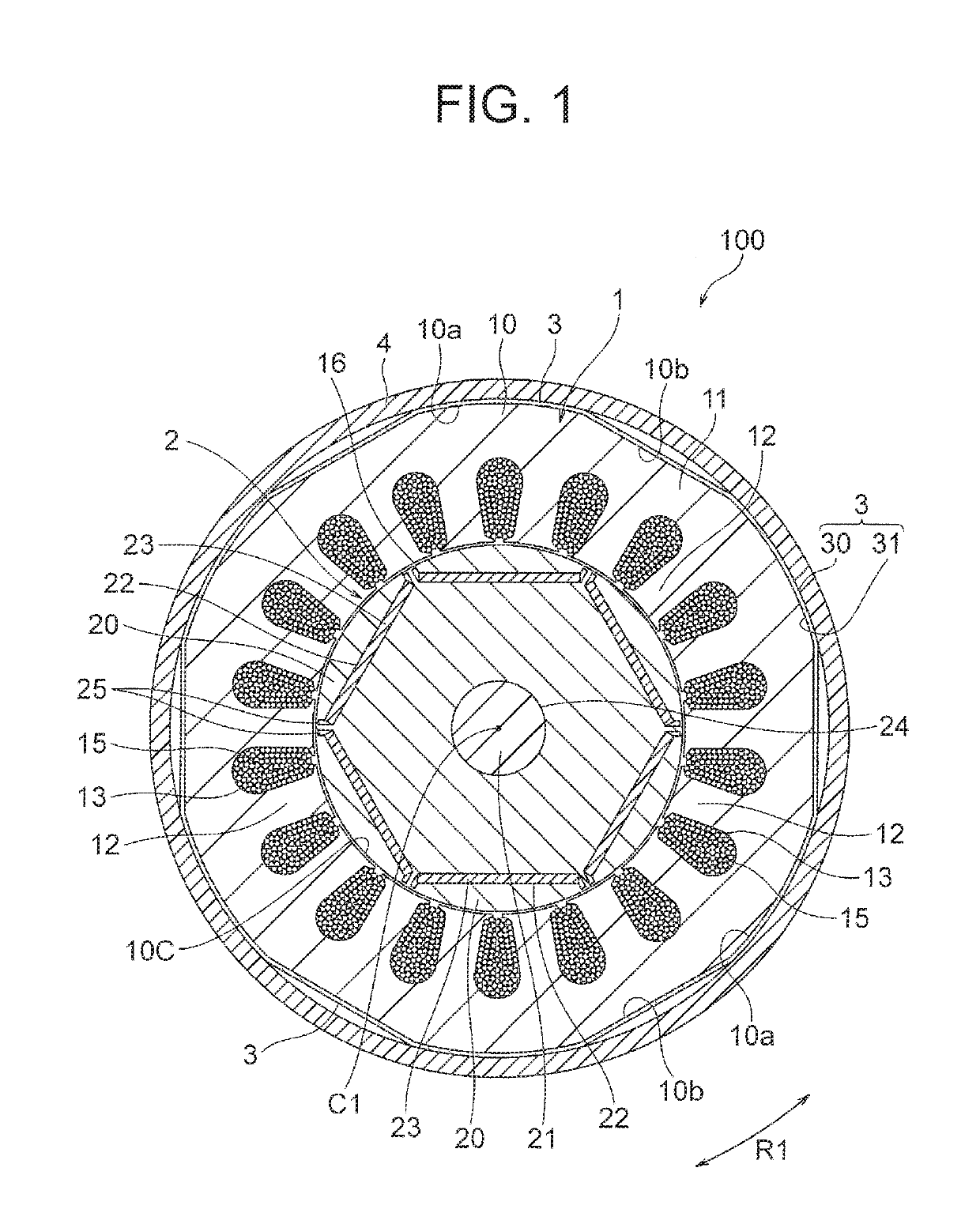
[0023]FIG. 1 is a sectional view illustrating a motor 100 according to a first embodiment. The motor 100 illustrated in FIG. 1 is mounted inside a cylindrical shell (casing) 4. The shell 4 is a part of a container of a product (for example, a scroll compressor 500 illustrated in FIG. 10) in which the motor 100 is mounted.
[0024]The motor 100 includes a rotatable rotor 2, and a stator 1 provided so as to surround the rotor 2. The stator 1 is mounted inside the above-described shell 4. An air gap 16 of, for example, 0.5 mm is provided between the stator 1 and the rotor 2.
[0025]The rotor 2 includes a rotor core 20 having a plurality of magnet insertion holes 22, and permanent magnets 23 disposed in the respective magnet insertion holes 22. The rotor core 20 includes an outer peripheral surface having a cylindrical shape about an axis line C1 serving as a center of rotation. A shaft hole 24 is formed at a center of the rotor core 20 in a radial direction. A shaft ...
second embodiment
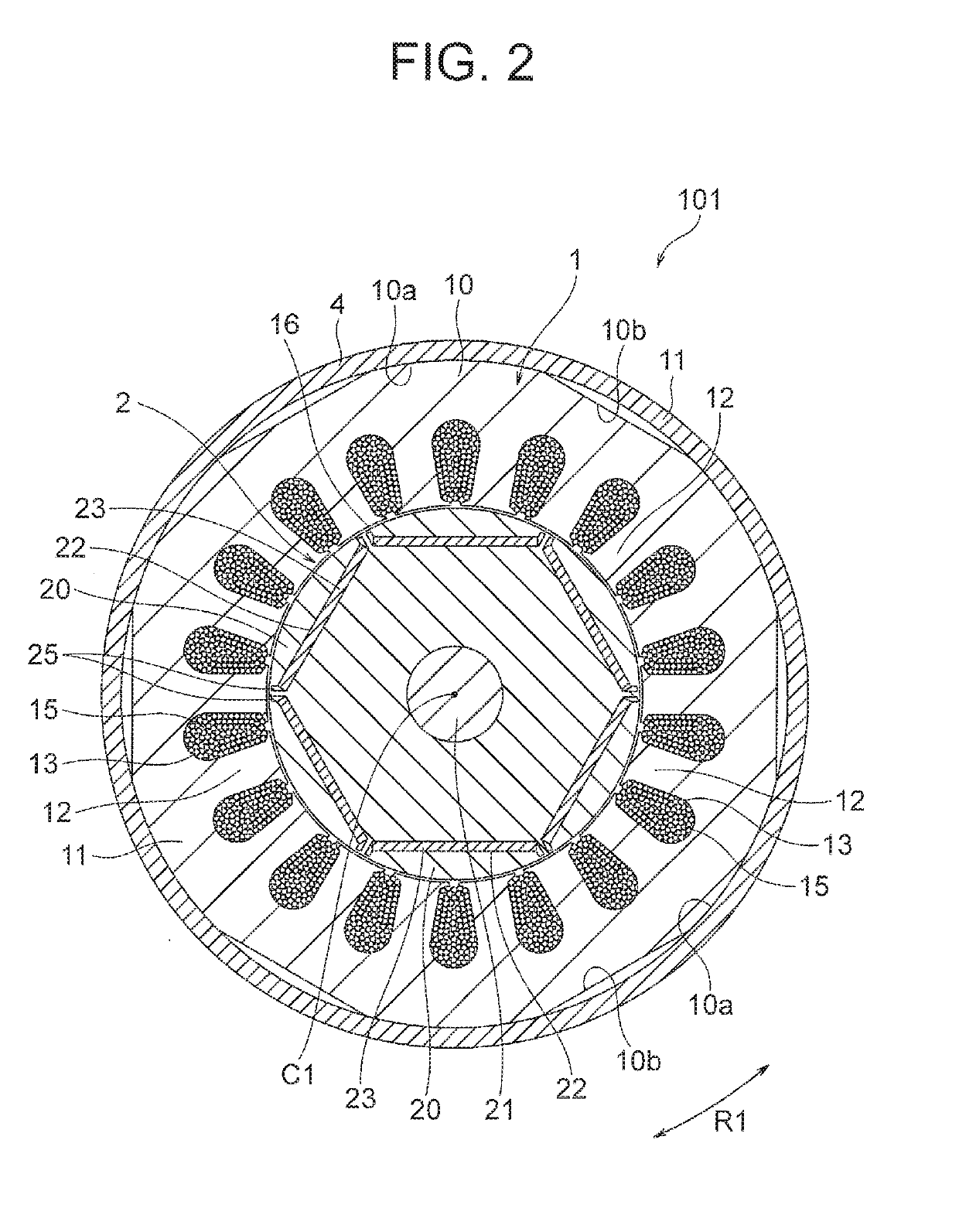
[0075]Next, a second embodiment of the present invention will be described. FIG. 8 is a sectional view illustrating a configuration of a motor 100A according to the second embodiment. In the above-described first embodiment, the nonmagnetic film 3 is fixed to the outer peripheral surface of the stator 1 before the stator 1 is fitted into the shell 4. In contrast, in this second embodiment, a nonmagnetic film 3A is fixed to the inner peripheral surface of the shell 4.
[0076]The nonmagnetic film 3A is fixed to the inner peripheral surface of the shell 4 by, for example, bonding. By fitting the stator 1 into the shell 4 by shrink fitting, a configuration in which the nonmagnetic film 3A is disposed between the outer peripheral surface of the stator 1 and the inner peripheral surface of the shell 4 is obtained. The material and the thickness of the nonmagnetic film 3A in the second embodiment are the same as those of the nonmagnetic film 3 in the first embodiment.
[0077]The nonmagnetic fi...
embodiment 3
[0081]Next, a third embodiment of the present invention will be described. FIG. 9 is a sectional view illustrating a configuration of a motor 100B according to the third embodiment. In the above-described first embodiment, the nonmagnetic film 3 is fixed to the entire area of the outer peripheral surface of the stator 1. In contrast, in this third embodiment, nonmagnetic films 3B are fixed only to cylindrical surfaces 10a which are parts of the outer peripheral surface of the stator 1.
[0082]The cylindrical surfaces 10a and the flat surfaces 10b are alternately formed on the outer peripheral surface of the stator core 10, as described in the first embodiment. The cylindrical surfaces 10a are in contact with the inner peripheral surface of the shell 4, and gaps are formed between the flat surfaces 10b and the inner peripheral surface of the shell 4. In this third embodiment, the nonmagnetic films 3B are disposed only on the cylindrical surfaces 10a. The material and the thickness of t...
PUM
 Abstract
Description
Claims
Application Information
 - R&D
- Intellectual Property
- Life Sciences
- Materials
- Tech Scout
- Unparalleled Data Quality
- Higher Quality Content
- 60% Fewer Hallucinations
Browse by: Latest US Patents, China's latest patents, Technical Efficacy Thesaurus, Application Domain, Technology Topic, Popular Technical Reports.
© 2025 PatSnap. All rights reserved.Legal|Privacy policy|Modern Slavery Act Transparency Statement|Sitemap|About US| Contact US: help@patsnap.com


