Communication devices and methods with beamforming training

a beamforming training and communication device technology, applied in the field of communication devices, can solve the problems of lack of knowledge, strong free space path loss in the 60 ghz frequency range, and difficulty in beamforming training for association, so as to reduce the probability of collision in the association phase, the effect of increasing the antenna gain

Active Publication Date: 2019-10-17
SONY CORP
View PDF2 Cites 7 Cited by
  • Summary
  • Abstract
  • Description
  • Claims
  • Application Information

AI Technical Summary

Benefits of technology

[0007]It is an object to provide communication devices and corresponding communication methods yielding a higher antenna gain, enabling long-range association and data transmission, and / or reducing the collision probability in association phase.

Problems solved by technology

Communication systems in the 60 GHz frequency range suffer from strong free space path loss, which increases with frequency.
Beamforming training for association is however a challenging problem due to i) lack of any knowledge at one of the communication devices, e.g. at the access point (AP), about other communication devices, e.g. the stations (STAs), that may want to associate, and ii) relatively scarce knowledge at STAs about the “good” sectors on which they can listen on.
The problems with this approach are collision probability since APs listen omnidirectional so that frames from multiple STAs can collide, especially in dense scenarios, and coverage problems since the directivity gain at STAs can be significantly lower than at the AP or STAs can be far from the APs, in which case the beams transmitted by the STAs do not reach the APs.

Method used


Image

  • Communication devices and methods with beamforming training
  • Communication devices and methods with beamforming training
  • Communication devices and methods with beamforming training

Examples


case b

[0058]In case B, no AP has been detected and the STA may repeat the listing procedure with various directive beams continuously or at a later point in time.

[0059]It should be noted that the AP may perform no special operations during this training phase. The modifications are mainly on STA side. Therefore, this approach can reuse any BTI such as described in IEEE802.11ad and / or IEEE802.11ay BTI. No dedicated double directive or long range BTI is required. Given that spatial reuse is the main objective of a STA, it may receive with an omni-directional pattern during a single BTI phase like it is done according to IEEE802.11ad. Prerequisite is that the link budget is sufficient to overcome path loss.

[0060]In a second phase (also called association beamforming training phase), the STA TX and AP RX procedure takes place in various DD-A-BFT slots. During a single DD-A-BFT slot, the STA uses different transmit sectors, one for each SSW frame. The AP keeps its receiver pattern unchanged du...

first embodiment

[0062]First, the case shall be considered where reciprocity is available neither at AP nor at STA side. FIG. 5 shows a diagram of association beamforming training with a single STA. In each of the DD-A-BFT slots, the AP listens with a directive beam 60, 62, respectively (“first directive receive beam”). Each DD-A-BFT slot may have a different beam 60, 62 (it may be beneficial to use same receive beam in various DD-A-BFT slots, as will be explained later).

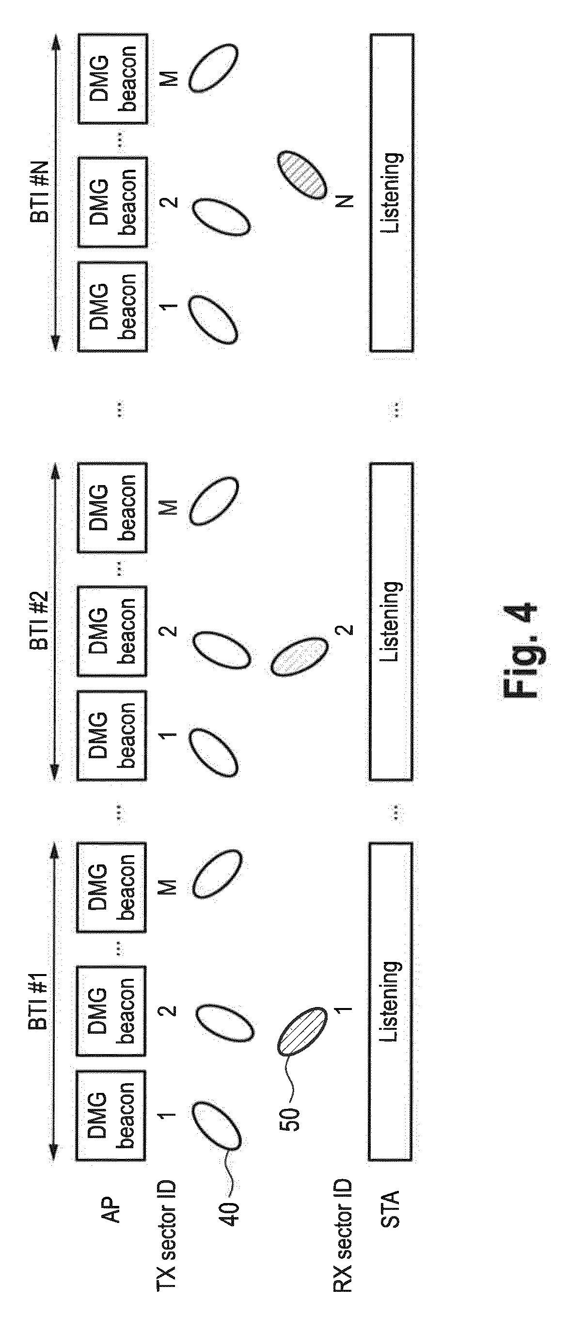
[0063]The STA is transmitting several SSW frames within one or more A-BFT slots, starting from the first A-BFT slot of the DD-A-BFT. In each DD-A-BFT slot, a STA can sweep through M different transmit patterns, i.e. use different directive beams 70 (“first directive transmit beams”). Thereby each SSW frame holds information about the best received AP transmit sector (TXAP, “second transmit beam information”) determined in the BTI phase (see FIG. 4) and the current transmit sector of the STA. In order to receive the SSW feedback (“re...

second embodiment

[0074]FIG. 6 shows a diagram of association beamforming training with a two STAs associating simultaneously. It is assumed that STA 1 and STA 2 have been able to associate in the first and second DD-A-BFT slot, respectively. If a SSW feedback has been received, both AP and STAs have knowledge of the best TX and RX sector ID to use for subsequent communications. Note that only TX sector information is required to be exchanged between AP and STA during SSW frames and SSW feedback, respectively.

[0075]In the example shown in FIG. 6, in a first sector sweep STA1 uses first directive transmit beams 70, STA2 uses first directive transmit beams 80 and AP listens using a first directive receive beam 60. Preferably, in the first directive transmit beams 70 and 80 the information about the best third transmit beam used by the AP in the beacon transmission interval for the respective STA (i.e. TXAP(STA1) and TXAP(STA2), “second transmit beam information”) is included.

[0076]If during the first s...


PUM


Abstract

A communication device, e.g. an access point, for RF-based communication with another communication device, e.g. a station, comprises antenna circuitry configured to transmit and receive RF signals and beamforming circuitry configured to perform beamforming. The beamforming circuitry controls the antenna circuitry to transmit data, in a beacon transmission phase prior to the beamforming training phase, using a set of third directive transmit beams in subsequent time slots and to listen, in the beamforming training phase, using a set of first directive receive beams in subsequent time slots that is different from the set of third directive transmit beams.

Description

BACKGROUNDField of the Disclosure[0001]The present disclosure relates to different communication devices, such as a mobile station and an access point, which are configured for RF-based communication with each other. The present disclosure further relates to corresponding communication methods.Description of Related Art[0002]Communication systems in the 60 GHz frequency range suffer from strong free space path loss, which increases with frequency. For instance, a 60 GHz communication system has roughly 22 dB higher attenuation compared to a communication system operating at 5 GHz. To overcome the increased path loss, 60 GHz or any mmWave communication system employs beamforming, i.e. transmitter and / or receiver feature a steerable phased-array antenna (PAA), which can form directive beams towards the other communication device. Such beams have typically a high directivity and are spatially very narrow. The directivity in main direction increases with the number of antenna elements p...

Claims


Application Information

Patent Timeline
Patent Type & Authority Applications(United States)
IPC IPC(8): H04B7/08H04B7/0452H04B7/06H04W48/16
CPCH04B7/0452H04B7/088H04W48/16H04B7/0695H04B7/0617H04W8/005
Inventor CIOCHINA, DANAHANDTE, THOMASLOGHIN, NABIL SVENFELLHAUER, FELIX
Owner SONY CORP
Why Eureka
Try Eureka