Supercharge Your Innovation With Domain-Expert AI Agents!

System and method for correcting conveyor belt misalignment

a technology of conveyor belt and system components, applied in the direction of conveyor parts, rollers, transportation and packaging, etc., can solve the problems of poor quality of conveyor belt splices, poor quality of conveyor belts, and so as to improve the effectiveness of correcting the misalignment of conveyor belts

Active Publication Date: 2019-10-24
SYNCRUDE CANADA LTD
View PDF8 Cites 1 Cited by
  • Summary
  • Abstract
  • Description
  • Claims
  • Application Information

AI Technical Summary

Benefits of technology

The present invention relates to correcting mis alignment of a conveyor belt relative to a pulley. It involves pivoting a rolling contact surface for the conveyor belt in a way that produces both a yaw and roll component of rotation. This results in a combined transverse pushing, torsional steering, and tilting effect that can more effectively correct the misalignment of the conveyor belt than any of these effects alone.

Problems solved by technology

Conveyor belts may become misaligned from their supporting pulleys and idler rollers due to a variety of factors: impact forces of the bulk material being dumped on the conveyor belt; uneven weight distribution of bulk materials on the conveyor belt; non-steady state loading of bulk materials on the conveyor belt; damage to or fouling of conveyor belt system components; poor quality of conveyor belt splices; uneven tension across the width of the conveyor belt; and temperature changes in the operating environment.
Conveyor belt misalignment accelerates wears of the conveyor belt, and can damage other components of the conveyor belt system.
Further, the downtime for inspecting and fixing misaligned conveyor belts can result in significant productivity loss.

Method used


Image

  • System and method for correcting conveyor belt misalignment
  • System and method for correcting conveyor belt misalignment
  • System and method for correcting conveyor belt misalignment

Examples


first embodiment

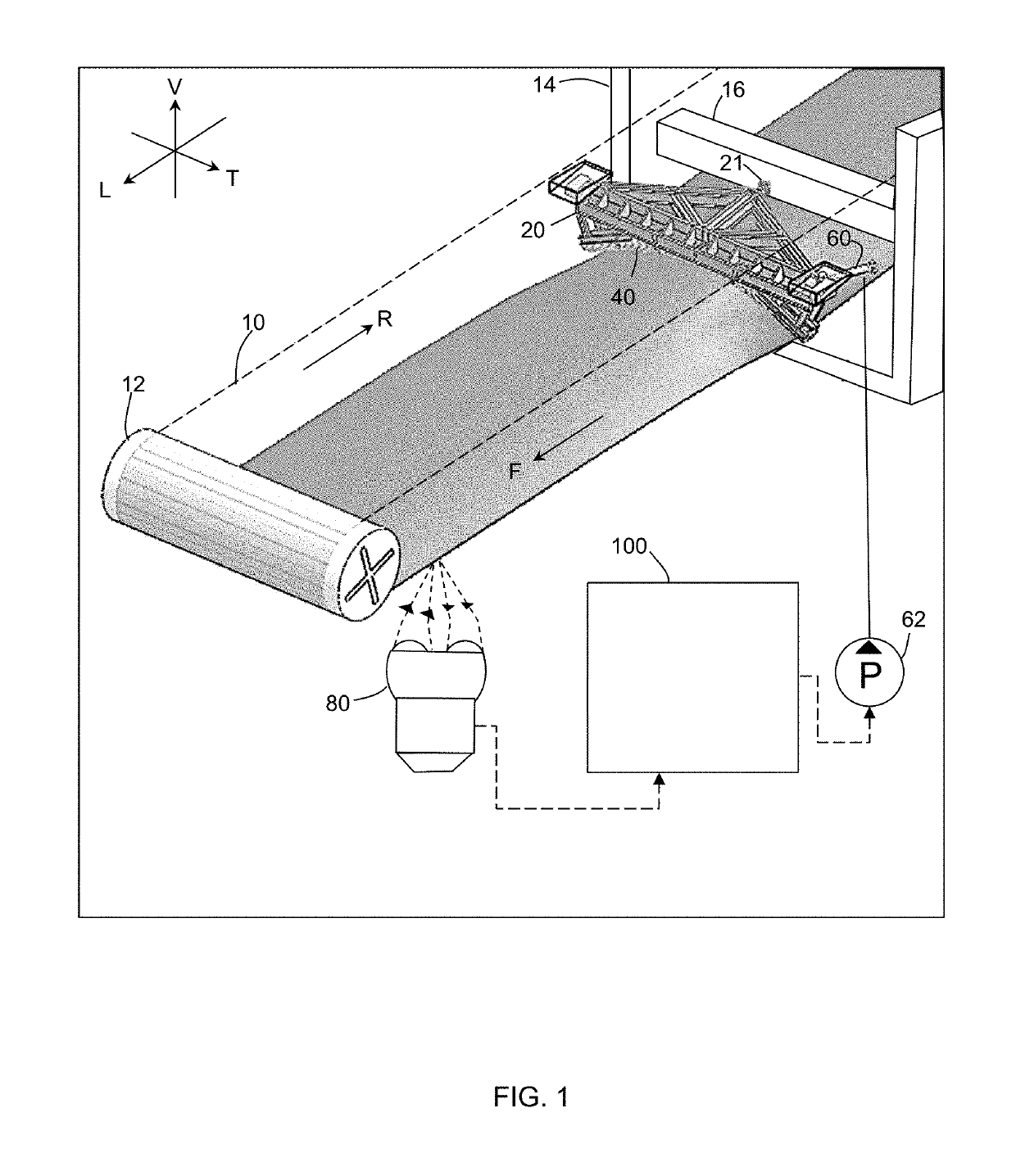
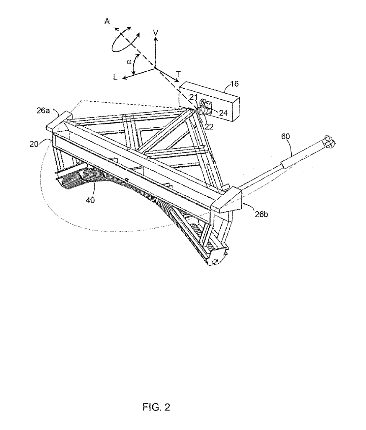
[0031]First embodiment. FIGS. 1 to 4B show a system of the present invention, together with a conveyor belt installation. For convenient description, FIG. 1 shows three mutually orthogonal references axes corresponding to a horizontal longitudinal direction (L), a horizontal transverse direction (T), and a vertical direction (V). These directions are used only to refer to relative spatial relationships between parts of the system. As such, the horizontal directions (L) and (T) may not be exactly horizontal, and the vertical direction (V) may not be exactly vertical in implementation of the invention.

[0032]Referring to FIG. 1, the conveyor belt installation by itself is conventional, and includes a conveyor belt (10) supported and driven by an end pulley (12) relative to a support frame (14). In an exemplary use, the conveyor belt installation is used for transporting mined oil sands ore, but the system is not limited to any particular use. The forward run of the conveyor belt (10) (...

second embodiment

[0051]Second embodiment. FIGS. 5 to 9 show a second embodiment of the apparatus of the present invention, in isolation from the conveyor belt installation. the system is similar to the first embodiment of the system shown in FIGS. 1 to 4B, with like elements being labelled with like reference characters. Accordingly, the following description focuses on certain differences of the second embodiment and its use and operation, as compared with the first embodiment.

[0052]In this second embodiment, the bearing members (26a, 26b) of the frame (20) do not directly engage the guide surfaces (28a, 28b). Rather, a rolling element a ball transfer unit (35a, 35b) is attached to each of the bearing members (26a, 26b). As shown in one embodiment in FIG. 8, the ball transfer unit (35a, 35b) includes a housing that contains a ball supported by bearings (concealed from view in the housing) that allow the ball to rotate relative to the housing in multiple directions, while transmitting load. Such bal...

third embodiment

[0057]Third embodiment. FIGS. 10 and 11 show a third embodiment of the apparatus of the present invention, in isolation from the conveyor belt installation. the system is similar to the first and second embodiments of the system, with like elements being labelled with like reference characters.

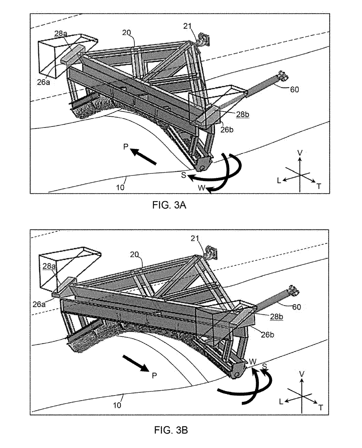
[0058]FIG. 10 shows the frame (20) pivoting from a neutral position (A) to a non-neutral position (B). (In FIG. 10, the neutral position (A) and the non-neutral position (B) are superimposed on each other for illustrative effect.) In the neutral position, the rolling contact surface provided by the idler rollers (40) is disposed symmetrically in relation to a properly aligned conveyor belt, so that the transverse pushing effect (P), the torsional steering effect (S) and the torsional tiling effect (W) are substantially nil. FIG. 11 shows a detailed view of the region of the apparatus near the pivot point, when the frame (20) pivots from the neutral position to the non-neutral position. (In FIG...


PUM


Abstract

A system for correcting transverse misalignment of a conveyor belt relative to a supporting pulley, includes a frame is pivotally attached to a stationary member. A guide surface engages the frame to guide pivoting of the frame about the pivot point simultaneously about a vertical axis and a longitudinally aligned axis. Idler rollers rotatably mounted on the frame define a rolling contact surface for the conveyor belt, which is concavely-shaped in a transversely-extending vertical plane. The pivoting of the frame causes the surface to impart a combined transverse pushing effect, torsional steering effect, and torsional tiling effect on the conveyor belt. An actuator applies a force to pivot the frame about the axis. A computer determines an amount of the misalignment based on a signal from a sensor, and automatically controls the actuator to pivot the frame, depending on the determined amount of the misalignment.

Description

FIELD OF THE INVENTION[0001]The present invention relates to systems and methods for correcting conveyor belt misalignment.BACKGROUND OF THE INVENTION[0002]Conveyor belt systems are used in a variety of industrial operations to transport bulk materials, including oil sand ores. Conveyor belts may become misaligned from their supporting pulleys and idler rollers due to a variety of factors: impact forces of the bulk material being dumped on the conveyor belt; uneven weight distribution of bulk materials on the conveyor belt; non-steady state loading of bulk materials on the conveyor belt; damage to or fouling of conveyor belt system components; poor quality of conveyor belt splices; uneven tension across the width of the conveyor belt; and temperature changes in the operating environment. Conveyor belt misalignment accelerates wears of the conveyor belt, and can damage other components of the conveyor belt system. Further, the downtime for inspecting and fixing misaligned conveyor be...

Claims


Application Information

Patent Timeline
IPC IPC(8): B65G39/16
CPCB65G39/16
Inventor CARNIATO, MICHAELWOLFE, DANPOLAK, MARKWU, YUXIANG (ISAAC)MOON, SOON WON
Owner SYNCRUDE CANADA LTD
Features
  • R&D
  • Intellectual Property
  • Life Sciences
  • Materials
  • Tech Scout
  • Unparalleled Data Quality
  • Higher Quality Content
  • 60% Fewer Hallucinations
Learn More