Ultrasonic cutter detection method and device

a detection method and ultrasonic cutter technology, applied in the field of detection, can solve the problems of low detection efficiency, inconvenient large-scale detection, and damage to processed parts and even machines, and achieve the effects of avoiding adverse effects, low production efficiency, and anti-fatigue capability

Active Publication Date: 2019-10-31
DALIAN UNIV OF TECH
View PDF0 Cites 7 Cited by
  • Summary
  • Abstract
  • Description
  • Claims
  • Application Information

AI Technical Summary

Benefits of technology

[0030]The present disclosure can realize the fall-of-potential detection method, the frequency amplitude detection method, the free mode detection method and the pressure mode detection method; the anti-fatigue capability of the ultrasonic cutter can be accurately judged by using the present disclosure; the cutter that does not have the anti-fatigue fracture capability is determined as unqualified cutter, and the cutter that has the anti-fatigue fracture capability is determined as qualified cutter and put into production; the present disclosure can avoid the adverse effects of low production efficiency and the like caused by the unqualified ultrasonic cutter fractured in the production process. In the present disclosure, using differences of the ultrasonic cutter surface in micro-cracks geometries and crack directions that result in different degrees of sensitivity of the track to different ultrasonic vibration modes, combined with the fall-of-potential method and the frequency amplitude detection method, can improve a detection rate of the unqualified ultrasonic cutter and a detection velocity.

Problems solved by technology

If there are micro cracks in the cutter, then under high-frequency forced vibration, the crack extension may lead to the fracture of the cutter, which is prone to cause the damage of processed parts and even a machine tool.
This detection method has low efficiency and is not suitable for large-scale detection.
This method is also not suitable for the detection of the ultrasonic cutter.
If the cutter does not have defects such as crack at the beginning of use, but only a metallographic structure is not strong enough, the cutter may also be fractured with load at high frequency, and the ultrasonic cutter cannot be accurately detected by this method.
If only the fall-of-potential method is used in the crack detection of the ultrasonic cutter, there may be large errors.
However, ultrasonic cutter may cause the opening and closing of the crack under stress and vibration.

Method used


Image

  • Ultrasonic cutter detection method and device
  • Ultrasonic cutter detection method and device
  • Ultrasonic cutter detection method and device

Examples


embodiment 1

[0046]A method for detecting an ultrasonic cutter comprises the following steps:

[0047]preliminary detection:

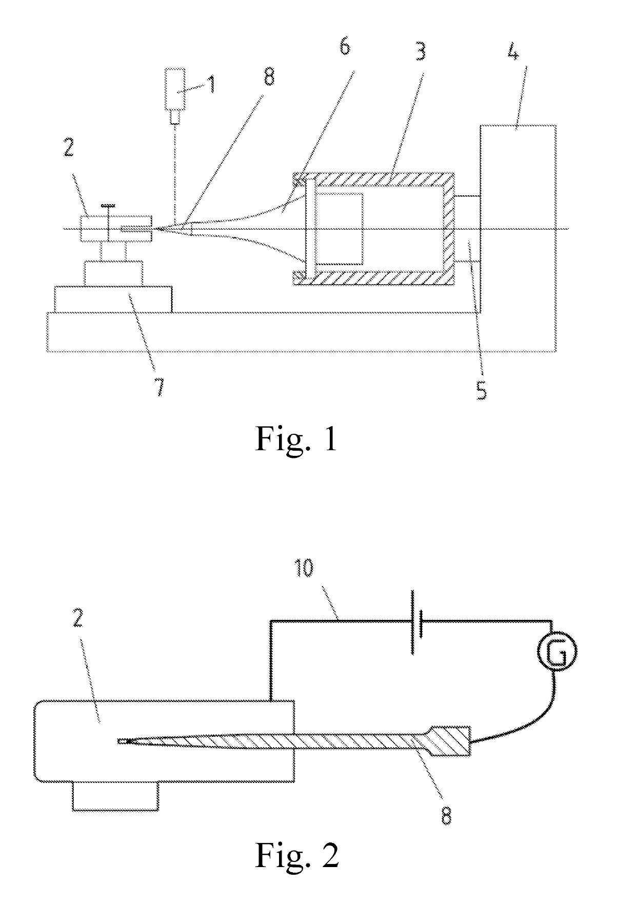
[0048]frequency amplitude detection: installing an ultrasonic cutter 8 on an ultrasonic amplitude transformer 6 capable of rotating along an axial direction, turning on the ultrasonic power supply to enable the ultrasonic cutter 8 to be in a resonant state, collecting the resonant frequency and amplitude of the blade on one side of the ultrasonic cutter 8 by a laser displacement sensor 1, then rotating (180°) the ultrasonic amplitude transformer 6 and the ultrasonic cutter 8; collecting the resonant frequency and the amplitude of the blade of the other side of the ultrasonic cutter 8 in the same way; and if the resonant frequencies and the amplitudes collected twice all fluctuate within a normal range, determining that the ultrasonic cutter 8 passes the preliminary detection;

[0049]fall-of-potential detection: installing the ultrasonic cutter 8 on the ultrasonic amplitude trans...

embodiment 2

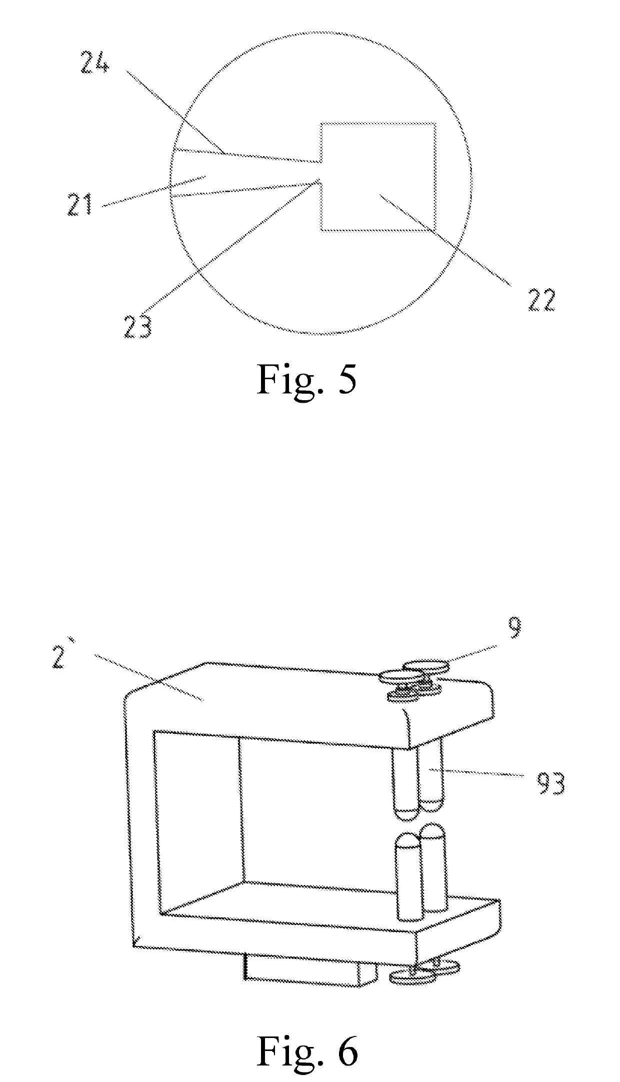
[0070]As shown in FIG. 6, FIG. 8, FIG. 10 and FIG. 11, an ultrasonic cutter detection device and method, it differs from the device and method disclosed in embodiment 1 in that the ultrasonic cutter detection head 2′ is U-shaped, the opening of the ultrasonic cutter detection head 2′ is provided with four force adjustment knobs 9, every two force adjustment knobs 9 form a group and are oppositely arranged to the other two force adjustment knobs, the force adjustment knob 9 comprises a bolt 91, a spring 92 and a contact rod 93 contacted with the ultrasonic cutter 8, which are sequentially connected, and the ultrasonic cutter detection head 2′ is provided with a hole 94 through which the contact rod passes. The bolt 91 is connected with the ultrasonic cutter detection head 2′ through a bolt seat 95.

[0071]In this embodiment, an axial detection head 2′ is adopted, the axial detection head is in open-type contact with the blade of the ultrasonic cutter 8, a contacted part of the contact ...

embodiment 3

[0073]As shown in FIG. 7, FIG. 8, FIG. 10 and FIG. 11, a device for detecting an ultrasonic cutter detection device and method, it differs from the device and method disclosed in embodiment 1 in that:

[0074]A cross section of the ultrasonic cutter detection head 2″ is U-shaped, the opening of the ultrasonic cutter detection head 2″ is provided with two force adjustment knobs 9, the two force adjustment knobs 9 are oppositely arranged to each other, the force adjustment knob 9 comprises a bolt 91, a spring 92 and a contact rod 93 contacted with the ultrasonic cutter 8, which are sequentially connected, the ultrasonic cutter detection head 2″ is provided with a hole 94 through which the contact rod 93 passes, the bolt 91 is connected with the ultrasonic cutter detection head 2″ through a bolt seat 95, and the other end of the contact rod 93 is always retained in the hole 94.

[0075]A contacted part of the contact rod 93 contacted with the ultrasonic cutter 8 is made of nylon and is elect...


PUM

PropertyMeasurementUnit
forceaaaaaaaaaa
ultrasonic cutter detectionaaaaaaaaaa
resonant frequencyaaaaaaaaaa

Abstract

An ultrasonic cutter detection method and device, the method comprises the following steps: preliminary detection: frequency amplitude detection and fall-of-potential detection, if the ultrasonic cutter fails the above two detection solutions in the preliminary detection, repeating the two detections; if the ultrasonic cutter still fails the above two detection solutions, the ultrasonic cutter is judged to be unqualified; and reinspection: free modal detection and pressure modal detection. Using differences of the ultrasonic cutters surface in micro-crack directions that result in different degrees of sensitivity of crack to different ultrasonic vibration modes, combined with the fall-of-potential method and frequency amplitude detection method, a detection rate and a detection velocity of an unqualified ultrasonic cutter can be improved.

Description

TECHNICAL FIELD[0001]The present disclosure relates to the detection field, and more particularly, to a method for detecting an ultrasonic cutter and a corresponding detection device.BACKGROUND ART[0002]Ultrasonic-assisted cutting machining technology is increasingly widely used in national economic production and life. Different from traditional machining, in an ultrasonic-assisted machining, a cutter not only performs a cutting motion and bears a cutting force, but also performs different forms of vibrating such as high-frequency stretching / compression, torsion, oscillation and the like under the drive of an ultrasonic vibration system. High-frequency vibration puts forward higher requirements on the quality of the cutter, especially the surface integrity of the cutter. If there are micro cracks in the cutter, then under high-frequency forced vibration, the crack extension may lead to the fracture of the cutter, which is prone to cause the damage of processed parts and even a mach...

Claims


Application Information

Patent Timeline
Patent Type & Authority Applications(United States)
IPC IPC(8): G01N29/12G01N29/22G01N27/00
CPCG01N2291/014G01N27/00G01N29/227G01N2291/023G01N29/12G01N2291/0289G01H9/00G01N2291/015G01N29/11G01N2291/0258G01N29/043G01N29/2418
Inventor KANG, RENKEDONG, ZHIGANGZHU, XIANGLONGWANG, YIDANZHANG, XUNZHOU, PINGJIA, ZHENYUAN
Owner DALIAN UNIV OF TECH
Why Eureka
Try Eureka