Projection system and projection-type image display apparatus

Active Publication Date: 2019-10-31
SEIKO EPSON CORP
View PDF0 Cites 6 Cited by
  • Summary
  • Abstract
  • Description
  • Claims
  • Application Information

AI Technical Summary

Benefits of technology

[0102]In the optical path deflection system 60, the first optical path deflector AP1 and the second optical path deflector AP2 are so disposed as to be parallel to each other, in the example shown in FIGS. 2 to 6. That is, the optical axis OA′ of the first optical group 40a and the optical axis OA2 of the second optical group 40b, which is the optical axis deflected by the optical path deflection system 60, are parallel to each other, and the direction in which the optical axis OA′ extends coincides with the direction in which the optical axis OA2 extends. In this case, the projection system 40 can be accommodated in the enclosure SC, which has a roughly square shape, as shown, for example, in FIG. 3. In contrast, it is conceivable as another variation that the first optical path deflector AP1 and the second optical path deflector AP2 incline with respect to each other, as shown by way of example in FIGS. 8A and 8B, which correspond to FIGS. 4 and 3, respectively. In the example shown in FIGS. 8A and 8B, the first optical path deflector AP1 and the second optical path deflector AP2 incline by 7.5° with respect to each other. In this case, for example, the lateral width of the enclosure SC can be further reduced by folding the ramp portion of the optical engine.
[0103]A projection system according to a second embodiment and a projection-type image display apparatus incorporating the projection system will be described below in detail with reference to FIGS. 9 to 11A and 11B. The present embodiment is a variation of the first embodiment and is the same as the first embodiment except that the second optical group is formed of a plurality of lenses in the projection system. Therefore, portions having the same functions as those in the first embodiment have the same names and reference characters and will not be described in detail.
[0104]FIG. 9 is a plan view showing a projector in which the projection system according to the present embodiment or Example 4 is in

Problems solved by technology

In a case where the projection system is formed only of a refractive optical system, as in JP-A-2007-147970, however, providing a very wide field angle undesirably requires a very large lens particularly located on an enlargement side.
In JP-A-2006-235516, however, generation of an intermediate image causes an increase in

Method used


Image

  • Projection system and projection-type image display apparatus
  • Projection system and projection-type image display apparatus
  • Projection system and projection-type image display apparatus

Examples


first embodiment

[0041]A projection system according to a first embodiment of the invention and a projection-type image display apparatus incorporating the projection system will be described below in detail with reference to the drawings.

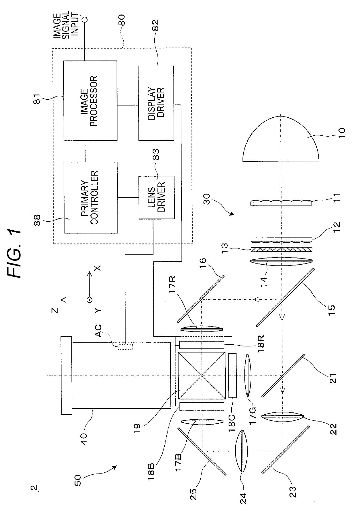
[0042]A projector 2, which is a projection-type image display apparatus incorporating the projection system according to the first embodiment, includes an optical system section 50, which projects image light, and a circuit apparatus 80, which controls the action of the optical system section 50, as shown in FIG. 1.

[0043]In the optical system section 50, a light source 10 is, for example, an ultrahigh-pressure mercury lamp and emits light containing R light, G light, and B light. The light source 10 may instead be a discharge light source other than an ultrahigh-pressure mercury lamp or a solid-state light source, such as an LED and a laser. A first optical integration lens 11 and a second optical integration lens 12 each have a plurality of lens elements arranged ...

second embodiment

[0103]A projection system according to a second embodiment and a projection-type image display apparatus incorporating the projection system will be described below in detail with reference to FIGS. 9 to 11A and 11B. The present embodiment is a variation of the first embodiment and is the same as the first embodiment except that the second optical group is formed of a plurality of lenses in the projection system. Therefore, portions having the same functions as those in the first embodiment have the same names and reference characters and will not be described in detail.

[0104]FIG. 9 is a plan view showing a projector in which the projection system according to the present embodiment or Example 4 is incorporated in the enclosure and corresponds to FIG. 3. FIGS. 10 and 11A are each a configuration diagram and light ray diagram of the portion from the object plane to the concave reflection mirror in the projection system and correspond to FIGS. 4 and 5, respectively. FIG. 11B is a rear...

example 1

[0156]Table 1 shown below shows data on the lens surfaces in Example 1.

TABLE 1  F 2.88FNo 2.44  ω 71.8Surface EccentricitynumberRDNdVdH(rotation)OBJInfinity6.060  1Infinity22.9201.5163364.1  2Infinity1.000  329.1225.9291.9228620.911.47  4−53.4810.15011.12  530.4947.0001.4970081.59.50  6−14.9591.0001.9228620.97.96  722.2550.1507.25 *812.54.4911.4970081.57.26 *989.3790.1356.72 1013.9335.5001.4874970.26.20 11−11.011.0001.9004337.45.35 127.144.5001.7618226.54.92 13−67.8092.3134.85STOInfinity4.0004.63 15−18.8132.0001.8000029.84.96 16−13.423d165.20*1715.9143.5001.5311656.011.09*18−93.779d1811.37*19−34.8882.0001.5311656.011.92*2018.542d2012.72 21Infinity0.000Reflection−35.0surface 22Infinity−48.000−35.0 23Infinity0.000Reflection35.0surface 24Infinity37.00035.0*25−28.425d25Reflection35.10surface

[0157]In Table 1 shown above and the following tables, 10 raised to some power (1.00×10+18, for example) is expressed by using E (1.00E+18, for example).

[0158]Table 2 shown below shows aspheric coeff...


PUM


Abstract

A first optical group that forms an intermediate image and a second optical group that enlarges and projects the intermediate image formed by the first optical group satisfy a variety of conditions. Therefore, first of all, in a case where a projection system is incorporated in a projector, an ultrawide field angle that allows enlargement and projection of an image at a half angle of view of 50° or greater is achieved. Further, an optical path deflection system including two optical path deflectors is disposed between the first optical group and the second optical group to allow the optical path to be folded with deterioration in performance of the projection system suppressed.

Description

BACKGROUND1. Technical Field[0001]The present invention relates to a projection system suitable to be incorporated in a projection-type image display apparatus that enlarges and projects an image on an image display device, such as a projector, and a projection-type image display apparatus using the projection system.2. Related Art[0002]In recent years, a projection system used in a projector and capable of providing a large screen in short-distance projection has been proposed, as described, for example, in JP-A-2007-147970.[0003]In a case where the projection system is formed only of a refractive optical system, as in JP-A-2007-147970, however, providing a very wide field angle undesirably requires a very large lens particularly located on an enlargement side. In JP-A-2007-147970, the upper limit of the increased field angle is about a half angle of view of 60°. In contrast, for example, in JP-A-2006-235516, using a refractive optical system and a concave mirror allows an ultrawid...

Claims


Application Information

Patent Timeline
IPC IPC(8): G02B13/04G03B21/28
CPCG03B21/28G02B13/04G02B13/00G02B17/08G02B27/18G02B9/00G02B27/00
Inventor MINEFUJI, NOBUTAKA
Owner SEIKO EPSON CORP
Why Eureka
Try Eureka