Air- cooled heat exchanger cleaning and temperature control apparatus and method

a technology of air-cooled heat exchanger and temperature control apparatus, which is applied in the direction of lighting and heating apparatus, flush cleaning, cleaning using liquids, etc., can solve the problems of reducing efficiency, reducing viscosity or even freezing of process liquid in the tube, and reducing temperature. , to achieve the effect of convenient temperature control

Active Publication Date: 2019-11-14
SAUDI ARABIAN OIL CO
View PDF0 Cites 8 Cited by
  • Summary
  • Abstract
  • Description
  • Claims
  • Application Information

AI Technical Summary

Benefits of technology

[0030]In an alternative embodiment, each of the spray tubes is connected directly to the common manifold that extends transversely above the top row of the finned tubes of the ACHE. Assuming that the ACHE is comprised of X rows of finned tubes, either a corresponding number of “N” spray tubes will extend longitudinally above each of the rows of finned tubes, or optionally “N+1” rows will be employed with a row of spray tubes beneath the bottom row to assure thorough cleaning of all portions of the fins at each level. The latter arrangement may be desirable where the cooling is by forced draft and the lower-most row of finned tubes is subjected to dust, dirt and / or sand carried in the air from the environment below the ACHE supporting structure. In dry, dusty and / or sandy regions of the world, it is common to elevate the finned tubes and the entire ACHE assembly well above ground level where dust and sand are easily rendered airborne by passage of vehicles and / or windy conditions to avoid having excess dirt picked up by the fans and blown into the finned tube array.

Problems solved by technology

Problems associated with ACHE units in specific climates and environments include accumulation of dust on and between the heat exchange fins which reduces the efficiency of the heat exchange with the air passing through the unit; insufficient temperature differentials to achieve the desired cooling of the hot process liquid by heat exchange with the surrounding hot ambient air; and extremely cold environments, e.g., at night and / or seasonally, leading to more than the desired decrease in temperature of the process liquid which can result in an increase in viscosity or even the freezing of the process liquid in the tubes.
This can be a time-consuming and laborious operation and the lower level and / or interior portions of the finned tube array can be difficult to reach via the water stream and they therefore are not thoroughly cleaned.
Failure to regularly and thoroughly clean the fins can result in the buildup of deposits requiring the application of chemical cleaning agents which have an associated high cost and may cause corrosion of the metal tubes and the fins.
In addition to being expensive, the water jetting does not reach the tubes at the bottom of the bundle and may actually damage the fins in the upper row or rows of tubes due to the high pressure of the water jet.
The supporting substructure and equipment located beneath the tubes may also be subject to corrosion damage from this type of washing.
Although suitable for cleaning ACHE units, the apparatus of the prior art is limited to that purpose.

Method used


Image

  • Air- cooled heat exchanger cleaning and temperature control apparatus and method
  • Air- cooled heat exchanger cleaning and temperature control apparatus and method
  • Air- cooled heat exchanger cleaning and temperature control apparatus and method

Examples


Embodiment Construction

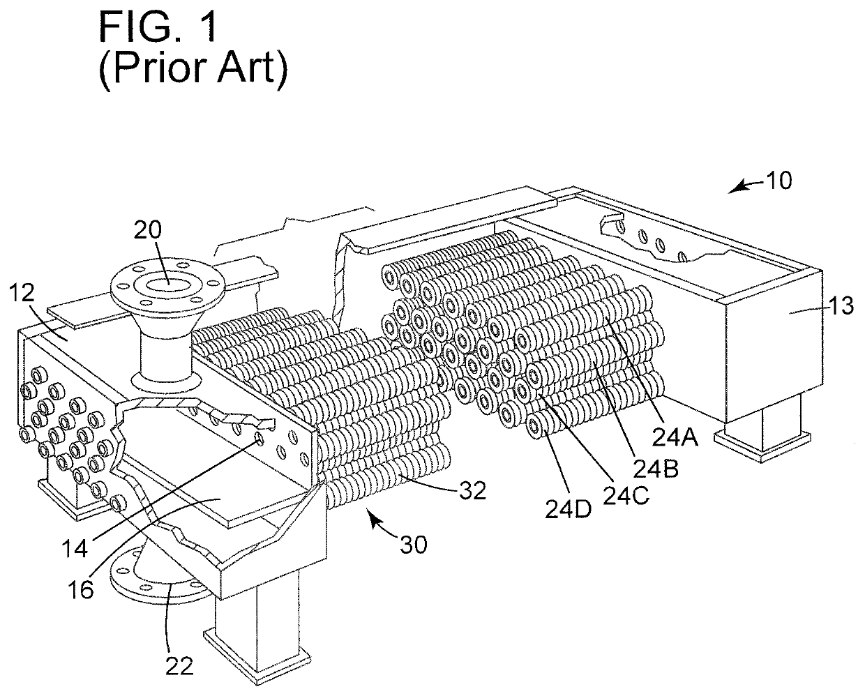
[0051]The apparatus, system and method of the invention will be described with reference to a horizontal ACHE that is configured generally as shown in the illustration of the representative prior art unit of FIG. 1. As illustrated, the ACHE 10 includes inlet header 12, tube sheet 14, a horizontally finned tube array 30 composed of a plurality of finned tubes 32 that are illustratively positioned in four horizontal rows (24A, 24B, 24C, 24D). The inlet header is divided by partition wall 16 and is fitted with hot process liquid inlet 20 and cooled process liquid outlet 22. Opposing header 13 returns the process liquid through the lower rows of finned tubes to the discharge portion of header 12.

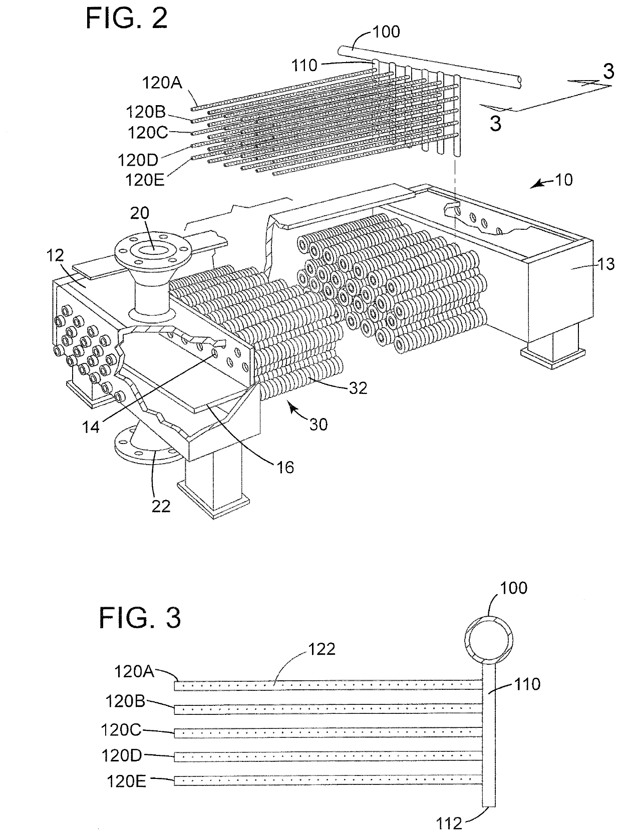
[0052]Referring now to FIG. 2, an ACHE of a construction similar to that of FIG. 1 is fitted with a common manifold 100 of the present system that is shown in the exploded position extending transversely above the top row of the array of finned tubes 30. As illustrated here, the common manifold ...


PUM


Abstract

A method and system for the maintenance and operation of air-cooled heat exchangers in climactic extremes of hot and cold ambient air temperatures which includes the permanent installation of a plurality of spray tubes provided with spaced-apart nozzles positioned between the finned heat exchange tubes and longitudinally aligned within the region of the finned-tube pitch. In one mode of operation, the forced air fan is stopped and temperature-controlled pressurized water with an optional cleaning agent is discharged from the nozzles to dislodge dirt and debris from the finned surfaces while simultaneously cooling the hot process liquid. When high ambient air temperatures preclude the forced air fans from achieving the required cooling of the process liquid passing through the ACHE, refrigerated pressurized cooled water and compressed air in the form of a mist is discharged from the nozzles. When low ambient air temperatures would reduce the temperature of the process liquid to an unacceptable level, pressurized heated air is discharged from the nozzles. Temperature sensors and associated automated programmed control systems can advantageously be employed to adjust the volume and temperature of the respective fluids discharged through the spray nozzles, or the system can be manually controlled by an operator based upon the temperature and pressure of the process fluid discharged from the ACHE.

Description

FIELD OF THE INVENTION[0001]This invention relates to the construction, maintenance and operation of air-cooled heat exchanger units for commercial and industrial use.BACKGROUND OF THE ART[0002]Air-cooled heat exchanger (ACHE) units are in widespread use in a wide variety of industries and geographical locations for treating process fluids, including liquids and gases. The hot process fluid to be cooled to a target temperature, or temperature range, flows through a bundle or array of finned tubes while the ambient cooling air flows across the outer surfaces to remove heat. The cooling air is propelled by fans in either a forced draft or induced draft configuration. Specially designed fins are attached to the outer surface of the tubes to create a large surface area for more effective cooling. The heat transfer rate is a function of the surface area of the fins and the velocity of the air flow, as well as the temperature differential. For convenience, the following description will r...

Claims


Application Information

Patent Timeline
Patent Type & Authority Applications(United States)
IPC IPC(8): F28G1/16B08B3/02B08B3/08F28G9/00F28G1/12
CPCF28G1/12B08B3/02F28G9/00F28D1/05341F28G1/166B08B3/08B08B2203/0217F28D1/05316F28F1/24F28F27/00F28F27/02F28G15/003B08B9/0323
Inventor AL-OTAIBI, ABDULLAH M.
Owner SAUDI ARABIAN OIL CO
Why Eureka
Try Eureka