Resistor element

Active Publication Date: 2019-11-14
TOMOEGAWA CO LTD
View PDF5 Cites 0 Cited by
  • Summary
  • Abstract
  • Description
  • Claims
  • Application Information

AI Technical Summary

Benefits of technology

The present invention allows for smaller, high-density mounting of resistor elements and can handle a wide range of resistance values. Additionally, the invention helps to reduce electromagnetic interference between neighboring resistor elements.

Problems solved by technology

However, even with the above-mentioned prior art, it cannot be said that sufficient miniaturization can be achieved in response to the demand for high-density mounting, and there is still room for improvement.

Method used


Image

  • Resistor element
  • Resistor element
  • Resistor element

Examples


first embodiment

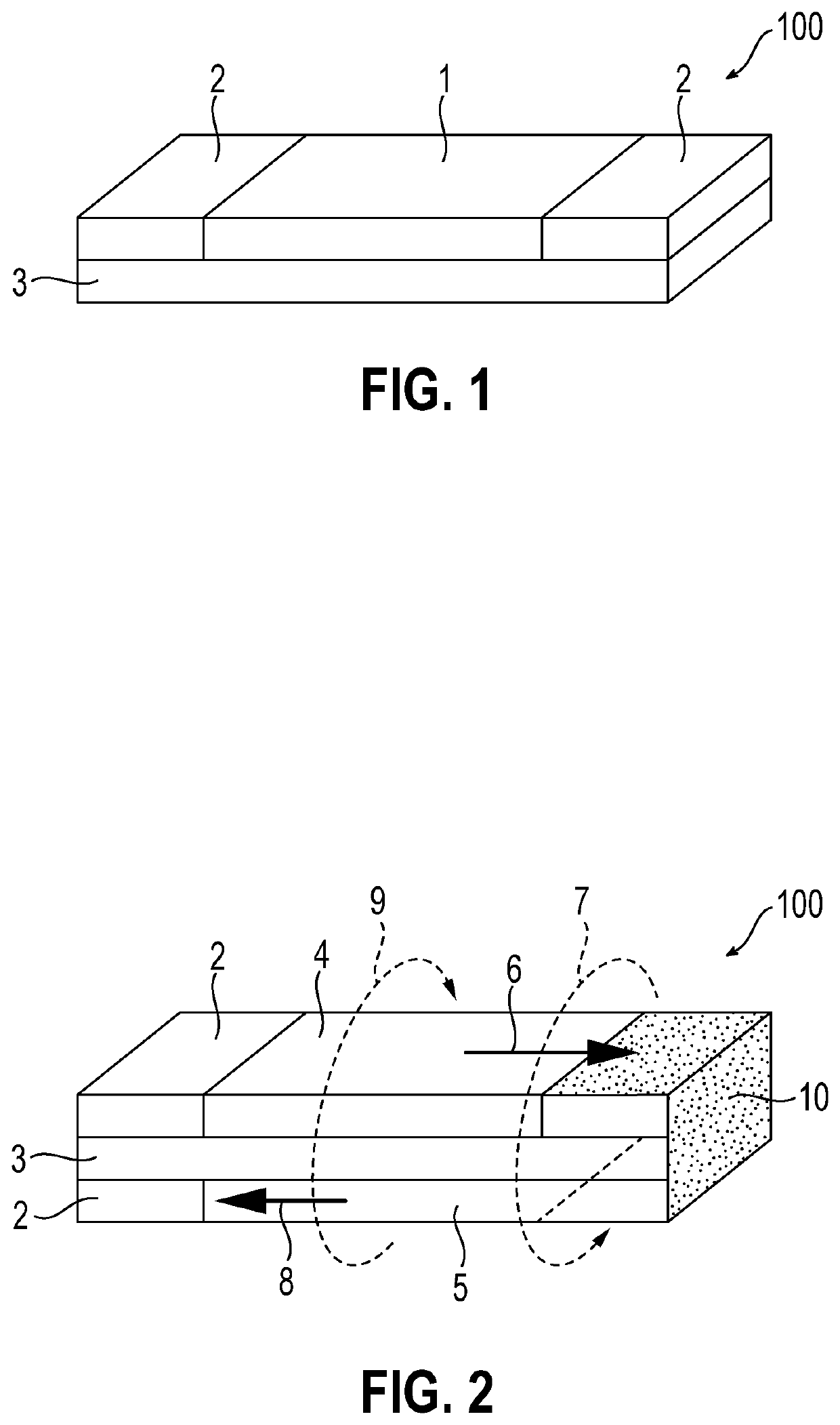
[0042]FIG. 1 is a schematic view showing one embodiment of a resistor element of the present invention. A resistor element 100 shown in FIG. 1 includes a resistor 1 which mainly contains metal fibers, electrodes 2 and 2 which are provided at both end portions of the resistor 1, and an insulating layer 3 which is laminated to the resistor 1 and the electrodes 2 and 2.

second embodiment

[0043]FIG. 2 is a schematic view showing another embodiment of a resistor element in which a first resistor 4 and a second resistor 5 are electrically connected by a connection portion 10. In the present embodiment, the electrodes 2 and 2 are formed at the end portion of the first resistor 4 and the second resistor 5, and the first resistor 4 and the second resistor 5 are electrically connected to each other at the connection portion 10. In addition, an insulating layer 3 is disposed in order to prevent the first resistor 4 and the second resistor 5 from being electrically connected other than the connection portion 10. By adopting such a structure, the miniaturization of the resistor clement can be realized, which can contribute to high-density mounting. At the same time, since the application direction of voltage of the first resistor 4 is different from the application direction of voltage of the second resistor 5 (in the present embodiment, the application directions are opposit...

third embodiment

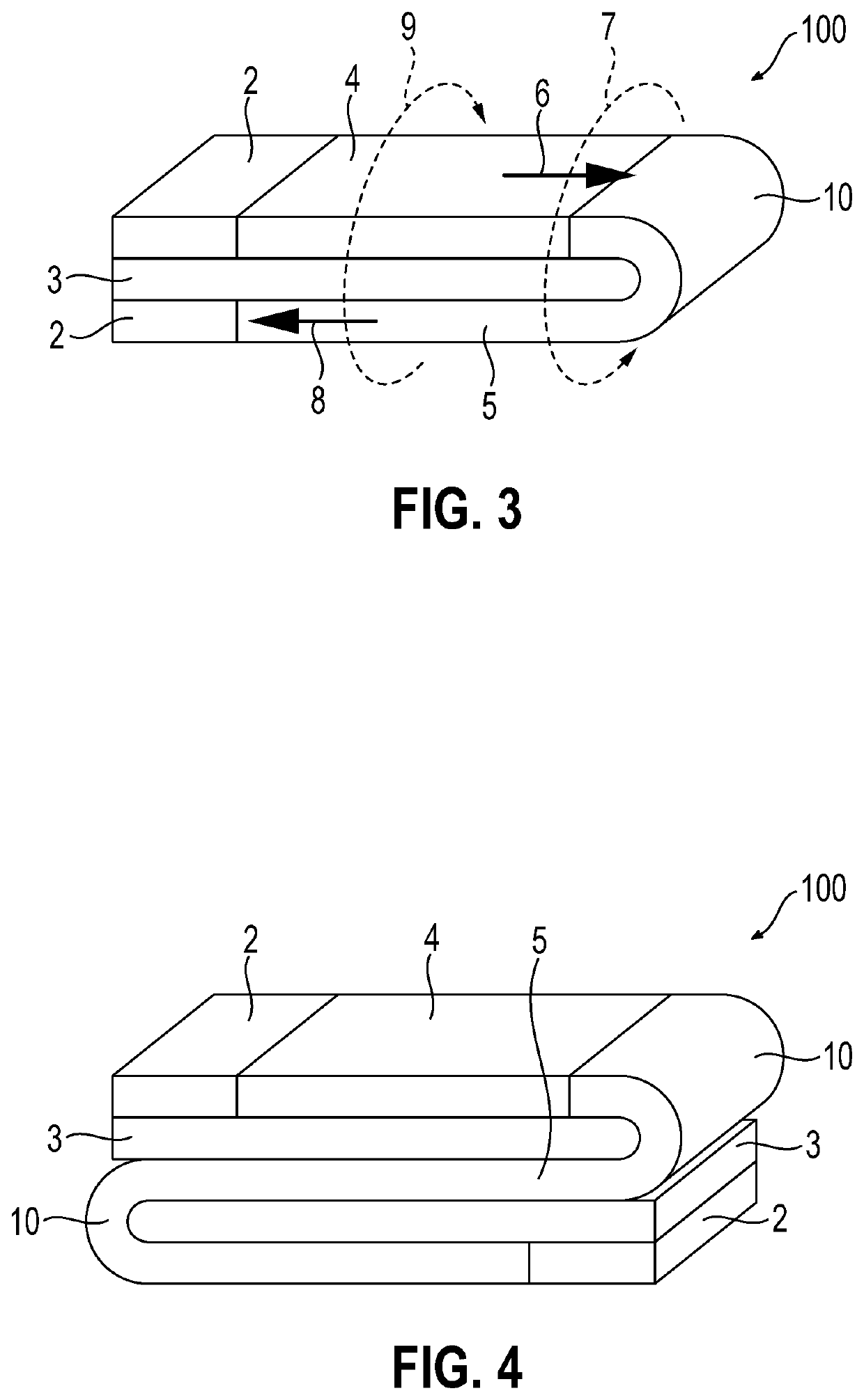
[0046]In addition, the first resistor 4, the second resistor 5, and the connection portion 10 may be continuous. In the present description, a continuous body refers to a state in which the other member is used to form the continuous both without binding in addition to a state in which one member is bent.

[0047]FIG. 3 shows a structure in which the first resistor 4, the second resistor 5, and the connection portion 10 are continuous. With such a structure, it is possible to eliminate the trouble of providing the connection portion 10 as in the embodiment shown in FIG. 2, which can contribute to of production of the resistor element.

[0048]In FIG. 3, the reference number 6 means the direction of the current flowing through the first resistor 4 and the reference number 7 means the magnetic field generated thereby. The reference number 8 means the direction of the current flowing through the second resistor 5, and the reference number 9 means the magnetic field generated thereby.

[0049]Th...


PUM


Abstract

An object of the present invention to provide a resistor element which can be mounted at a higher density and can cope with a wide range of resistance values, the present invention provides a resistor element including a resistor which mainly contains metal fibers, electrodes which are formed at an end portion of the resistor, and an insulating layer which is in contact with the resistor and the electrodes.

Description

FIELD OF THE INVENTION[0001]The present invention relates to a resistor element, and in particular to a resistor element suitable for high density mounting.BACKGROUND ART[0002]Miniaturized electronic components are beginning to be used in wiring plates for electrical and electronic devices. However, there is a demand for further miniaturization of electronic components, and for this purpose, there is an increasing demand for higher density packaging than before in a limited space.[0003]In such a background, as a metal plate resistor element having a compact chip type structure which can obtain a relatively high resistance value, a metal plate resistor which includes a flat plate resistor, and a pair of electrodes connected to both end portions of the flat plate resistor and disposed separately at a lower side of the flat plate resistor, and the flat plate resistor is fixed to the electrodes through an insulating layer has been suggested (Patent Document 1).[0004]In addition, as a me...

Claims


Application Information

Patent Timeline
IPC IPC(8): H01C3/10H01C13/00H01C17/07H01C1/012H01C7/22
CPCH01C17/07H01C1/012H01C7/22H01C3/10H01C13/00H01C3/06H01C1/14
Inventor OKUMURA, KATSUYAEGUCHI, KAZUHIROMURAMATSU, DAISUKE
Owner TOMOEGAWA CO LTD
Why Eureka
Try Eureka