Damping air spring with substantially fixed volume

a technology of air springs and substantially fixed volume, which is applied in the direction of shock absorbers, mechanical equipment, transportation and packaging, etc., can solve the problems of increasing adding additional maintenance and/or replacement costs to the axle/suspension system, and reducing the frequency dependence. , the effect of reducing the constraints on the operating range of air springs

Inactive Publication Date: 2019-11-21
HENDRICKSON USA L L C
View PDF0 Cites 7 Cited by
  • Summary
  • Abstract
  • Description
  • Claims
  • Application Information

AI Technical Summary

Benefits of technology

[0016]Objectives of the present invention include providing an air spring with damping features over a broader damping range, reducing frequency dependence, such that the air spring accommodates a broader range of loads and wheel motions to reduce the constraints on the air spring operating range.
[0017]Another objective of the present invention is to provide an air spring with damping features that utilizes fewer parts with a smaller air volume, so that the air spring weighs less, thereby reducing the cost of material, manufacturing, and repair.
[0018]A further objective of the present invention is to provide an air spring with damping features that reduces the need for larger air volumes to increase damping characteristics, thereby reducing the space required for the air spring in the axle / suspension system and providing increased space for heavier payload or cargo.
[0019]Yet another objective of the present invention is to provide an air spring with damping features that has improved damping while maintaining the desired air spring travel height.

Problems solved by technology

Although shock absorbers provide damping to the axle / suspension system, they undesirably add complexity and weight to the axle / suspension system.
Moreover, the shock absorbers are a service item of the axle / suspension system that require maintenance and / or replacement from time to time, adding additional maintenance and / or replacement costs to the axle / suspension system.
The restricted communication of air between the piston chamber and the bellows during heavy-duty vehicle operation provides damping to the axle / suspension system.
Prior art air springs with damping characteristics, while satisfactory for their intended purpose, have certain potential disadvantages, drawbacks, and limitations.
For example, because the prior art air springs only include openings located between the bellows chamber and the piston chamber, the damping range of the air spring is typically limited to a particular load or wheel motion.
These limitations on the damping range of the air spring restrict the ability to “tune” the damping for a given application.
In addition, prior art damping air springs typically require a large air volume, which undesirably increases the amount of space required by the axle / suspension system to accommodate prior art damping air springs, thereby increasing the weight of the axle / suspension system and reducing the space available in the heavy-duty vehicle for payload.
While the discrete internal bumper prevents damage to the air spring, the bumper is an additional part that increases the weight of the air spring, thereby increasing the weight of the axle / suspension system.
Because the spring rate of the air spring is determined by the volume of air contained in the air spring and because the discrete bumper takes up some volume of space inside the air spring, the prior art air spring with discrete bumper must be larger than an air spring that does not contain the discrete internal bumper, thus undesirably increasing the size of the air spring.

Method used


Image

  • Damping air spring with substantially fixed volume
  • Damping air spring with substantially fixed volume
  • Damping air spring with substantially fixed volume

Examples


Embodiment Construction

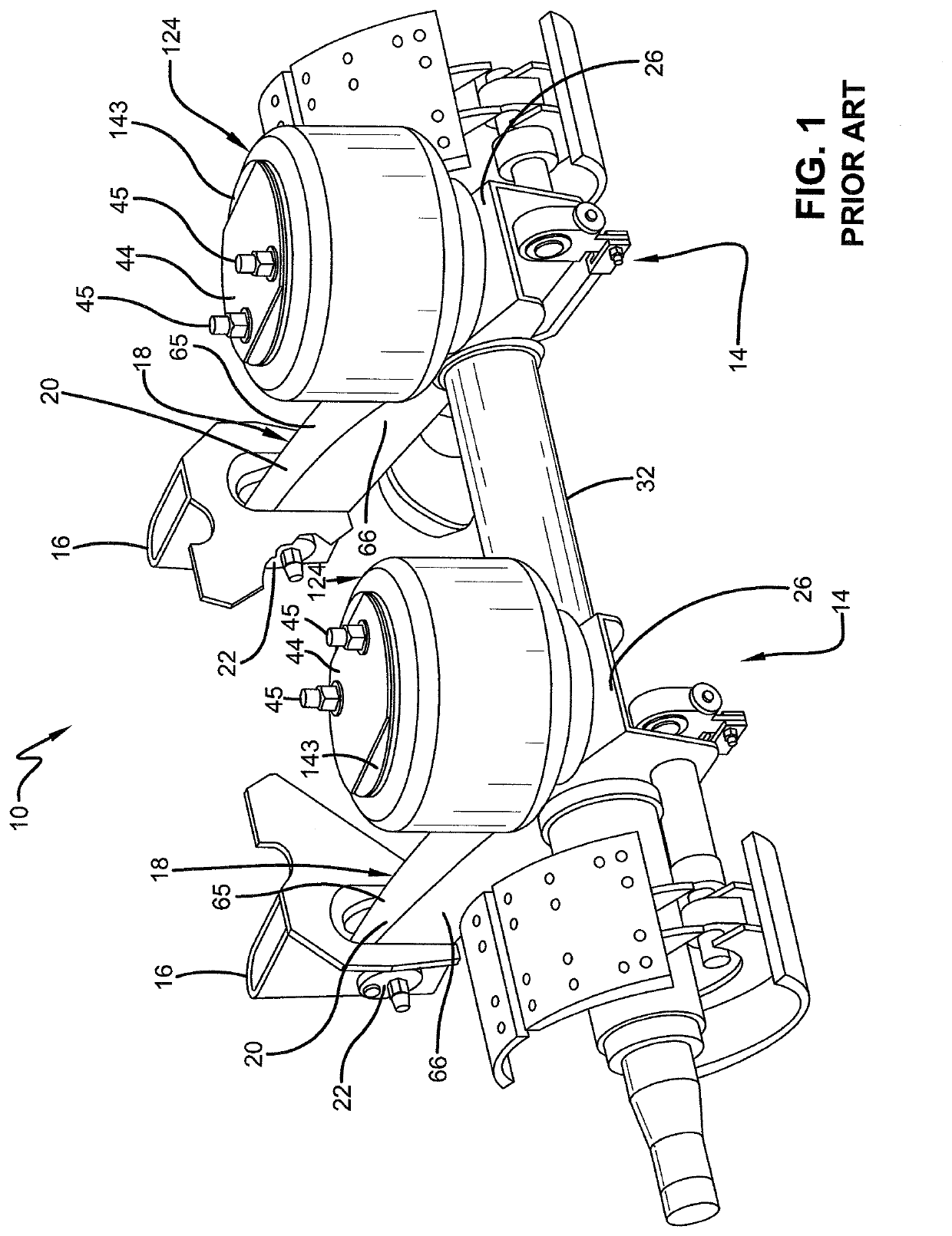
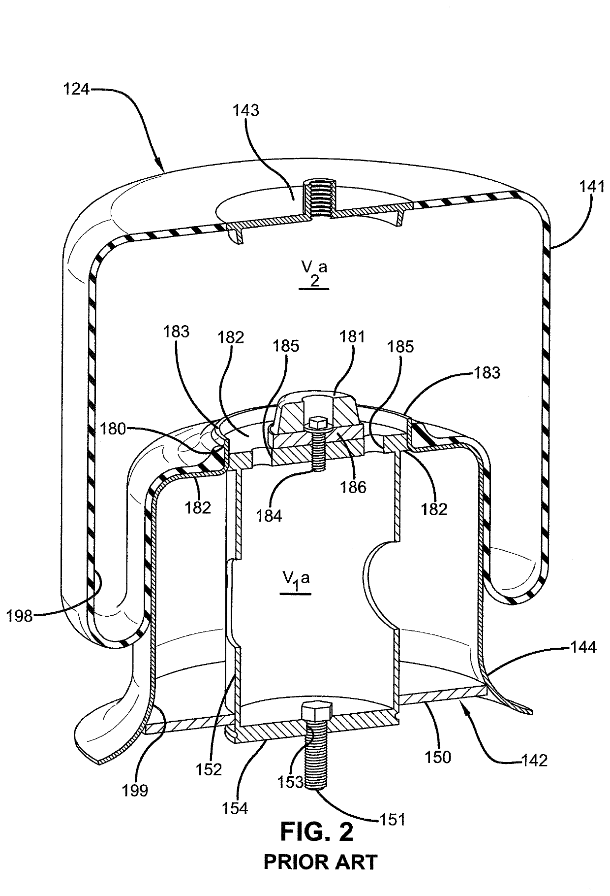
[0031]In order to better understand the environment in which the damping air spring for a heavy-duty vehicle of the present invention is utilized, a beam-type air-ride axle / suspension system 10 incorporating a prior art damping air spring 124 is shown in FIG. 1 and will be described in detail below.

[0032]It should be noted that axle / suspension system 10 typically includes a pair of mirror image suspension assemblies 14, each suspended from a respective longitudinally-extending transversely spaced-apart main member (not shown) of a heavy-duty vehicle (not shown). Because suspension assemblies 14 are mirror images and for the purposes of clarity and conciseness, only one of the suspension assemblies will be described below.

[0033]Suspension assembly 14 includes a beam 18 pivotally connected to a hanger 16, which is mounted on the main member of the heavy-duty vehicle. More specifically, beam 18 is generally formed having an upside-down integrally-formed U-shape with a pair of sidewalls...


PUM


Abstract

An air spring with damping characteristics for a suspension assembly of a heavy-duty vehicle includes a bellows chamber, a piston chamber, an intermediate chamber, and a first and second means for providing restricted fluid communication. The intermediate chamber is disposed at least partially within the bellows chamber and operatively connected to the bellows chamber and the piston chamber. The first means for providing restricted fluid communication is located between the bellows chamber and the intermediate chamber. The second means for providing restricted fluid communication is located between the piston chamber and the intermediate chamber. The first and second means for providing restricted fluid communication provide damping characteristics to the air spring during operation of the heavy-duty vehicle.

Description

CROSS-REFERENCE TO RELATED APPLICATION[0001]This application claims the benefit of U.S. Provisional Patent Application No. 62 / 673,408, filed May 18, 2018.BACKGROUND OF THE INVENTIONField of the Invention[0002]The present invention relates generally to the art of axle / suspension systems for heavy-duty vehicles. In particular, the present invention relates to axle / suspension systems for heavy-duty vehicles that utilize air springs to cushion the ride of the heavy-duty vehicle. More particularly, the present invention is directed to an air spring with damping characteristics for a heavy-duty vehicle axle / suspension system that utilizes a reduced air volume, which maintains air spring travel height and includes a bumper with an integrated flexible intermediate chamber, which is connected to the piston chamber and bellows chamber via staged openings to provide improved airflow control and promote damping of the axle / suspension system over a broad range of loads, wheel motions, and freque...

Claims


Application Information

Patent Timeline
Patent Type & Authority Applications(United States)
IPC IPC(8): B60G17/048B60G11/27F16F9/04F16F9/05F16F9/58
CPCB60G17/0485B60G2202/152B60G11/27F16F9/052F16F9/585F16F9/049B60G13/10B60G15/12B60G17/0521B60G17/08B60G2202/242B60G2202/30B60G2204/45B60G2206/424B60G2300/026B60G2500/10F16F9/0472F16F9/05
Inventor ZAWACKI, JEFF R.DELORENZIS, DAMON
Owner HENDRICKSON USA L L C
Why Eureka
Try Eureka