
Method for operating a brake system, and brake system

a technology of brake system and brake system, which is applied in the direction of brake system, vehicle sub-unit feature, brake components, etc., can solve the problem that the surface switchover is not performed during the forward stroke, and achieve the effect of eliminating the adverse effect of hydraulic management and higher forces

Pending Publication Date: 2019-11-21
CONTINENTAL TEVES AG & CO OHG
View PDF3 Cites 3 Cited by
  • Summary
  • Abstract
  • Description
  • Claims
  • Application Information

AI Technical Summary

Benefits of technology

This patent is for a braking system for vehicles that provides the driver with a familiar brake pedal feel. The system has a high-pressure generation capability during the forward stroke of the actuator, which is important for quickly displacing large volumes of brake fluid into the wheel brake circuits. The system also has a switchover to a smaller surface area for higher pressures with a given actuator force. The dimensions of the piston and force transmission rod are of the same dimensions to ensure the same maximum pressure during the forward and backward strokes. The system can utilize up to three hydraulically effective surfaces by controlling the discharge of brake fluid with the aid of the discharge valve. Overall, the patent presents technical advantages for optimizing braking performance.

Problems solved by technology

A disadvantage of this method is that such a surface switchover is not performed during the forward stroke.

Method used


Image

  • Method for operating a brake system, and brake system

Examples


Embodiment Construction

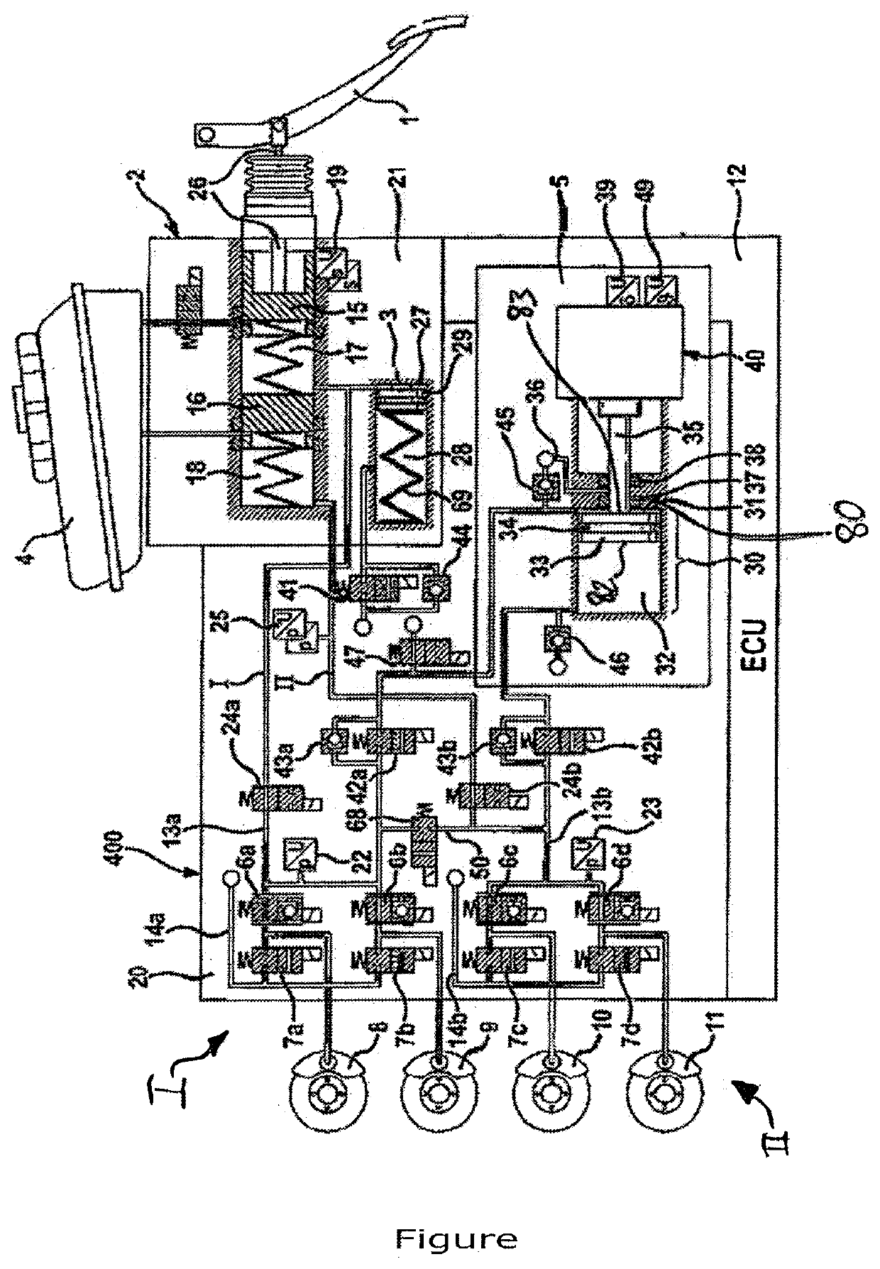
[0037]The illustrated brake system comprises a hydraulic pedal decoupling unit 2 which is actuatable by means of an actuation or brake pedal 1, a pedal feel simulator 3 which interacts with the hydraulic pedal decoupling unit 2, a pressure medium reservoir 4 which is assigned to the hydraulic pedal decoupling unit 2, an electrically controllable pressure provision device 5, an electrically controllable pressure modulation device 20, which comprises inlet and outlet valves 6a-6d, 7a-7d and to the output ports of which wheel brakes 8, 9, 10, 11 of a motor vehicle (not illustrated) are connected, and an electronic open-loop and closed-loop control unit 12, which serves for processing sensor signals and for activating the electrically controllable components.

[0038]In the “brake-by-wire” operating mode, the input ports of the inlet valves 6a-6d are supplied, via system pressure lines 13a, 13b, with a pressure which is referred to as system pressure, wherein pressure sensors 22, 23 are pr...


PUM


Abstract

A method for operating a motor vehicle brake system having hydraulic wheel brakes; an atmospheric pressure pressure medium reservoir; a pressure modulation unit setting wheel-specific brake pressures, an electrohydraulic pressure provision device connected to the pressure modulation unit and the pressure medium reservoir which outputs brake system pressure to the pressure modulation unit and draws in pressure medium from the reservoir; a first and second pressure activation valve connecting the pressure provision device to the pressure modulation device. A piston of the piston-cylinder arrangement separates two pressure spaces from one another. A pressure build-up occurs in the first pressure space during a backward movement of the piston and in the second pressure space during a forward movement of the piston. During a brake pressure build-up by a forward stroke of the piston, the activation valve is opened and the first pressure space is hydraulically separated from the pressure medium reservoir.

Description

CROSS REFERENCE TO RELATED APPLICATIONS[0001]This application is the U.S. National Phase Application of PCT International Application No. PCT / EP2017 / 083840, filed Dec. 20, 2017, which claims priority to German Patent Application No. 10 2017 200 420.7, filed Jan. 12, 2017, the contents of such applications being incorporated by reference herein.FIELD OF THE INVENTION[0002]The invention relates to a method for operating a brake system for motor vehicles, which brake system, in a brake-by-wire operating mode, can be activated both by the vehicle driver and independently of the vehicle driver, and is operated preferentially in the brake-by-wire operating mode, having hydraulic wheel brakes, wherein two wheel brakes are hydraulically assigned to a first brake circuit and two wheel brakes are hydraulically assigned to a second brake circuit, having a pressure medium reservoir which is under atmospheric pressure, having an electronic open-loop and closed-loop control unit, having a pressur...

Claims


Application Information

Patent Timeline
Patent Type & Authority Applications(United States)
IPC IPC(8): B60T13/74B60T13/66
CPCB60T13/686B60T13/146B60T13/662B60T13/741B60T2270/602F16D65/18B60T7/042B60T13/745B60Y2400/81
Inventor BESIER, MARCODRUMM, STEFANBÖHM, JÜRGEN
Owner CONTINENTAL TEVES AG & CO OHG
Learn More