
Optimal multi-electrode transcutaneous stimulation with high focality and intensity

Pending Publication Date: 2019-11-21
RGT UNIV OF CALIFORNIA
View PDF2 Cites 4 Cited by
  • Summary
  • Abstract
  • Description
  • Claims
  • Application Information

AI Technical Summary

Benefits of technology

The systems and methods in this patent offer better results in terms of directing intense light and focusing it on a specific area. These techniques can also be applied to stimulate other internal organs, such as the brain.

Problems solved by technology

However, it is invasive that needs surgery to implant electrodes into the body.
Due to large activated area, it is difficult to understand the underlying mechanism, for example which part of the activated area contributes to the treatment.
Further, the two-electrode montage is not able to target multiple sites simultaneously, which limits its effectiveness.
Therefore, it becomes inconvenient for stimulating a neural network dynamically.
However, because their stimulation parameters are just chosen by experience, the induced current is still not focused.
In addition, certain sensitive regions such as the bladder can not be avoided.
All of these together limit their capability of modulating the neuronal circuits precisely.
Generally, it is good at stimulating the radial orientation, and has difficulty in dealing with tangential orientation.
Another limitation lies in that when the target is not underneath any electrode, the ring configuration is not able to stimulate the target precisely.
In addition, it is not able to avoid certain regions either.
However, there has not been any work that uses optimization methods to obtain higher intensity or focal accuracy for transcutaneous spinal cord stimulation.
In tDCS / tACS, the conventional optimization methods either maximize intensity at the target, which results in very low focal accuracy of stimulation (e.g., maximum intensity method), or maximize the focal accuracy at the expense of low intensity (e.g., Linear Constrained Minimum Variance (LCMV)).
In addition, in the LCMV method and it variants, a hard constraint is enforced to meet the specified intensity and orientation at the target, which may lead to infeasible solution when the specified intensity is high or the target region is large.
In addition, the hard constraint limits the degree of freedom of the problem, which hinders it from obtaining a better solution with higher intensity or focality.
Another limitation of conventional optimization methods is that they require the clinician to specify location and intensity at the target, which is usually unknown in most applications.
However, the stimulation parameters chosen by this method is just empirical, and it is only able to deal with simple situations, such as cases in which a single focal source predominates.
It is unable to handle complicated cases, such as multiple targets, spatially extended targets with different orientations in different parts, or containing brain regions to be avoided.
From the hardware perspective, it is a big challenge to control a large number of stimulation channels independently.
Enabling necessarily high count of independently controlled current sources is challenging.

Method used


Image

  • Optimal multi-electrode transcutaneous stimulation with high focality and intensity
  • Optimal multi-electrode transcutaneous stimulation with high focality and intensity
  • Optimal multi-electrode transcutaneous stimulation with high focality and intensity

Examples


Embodiment Construction

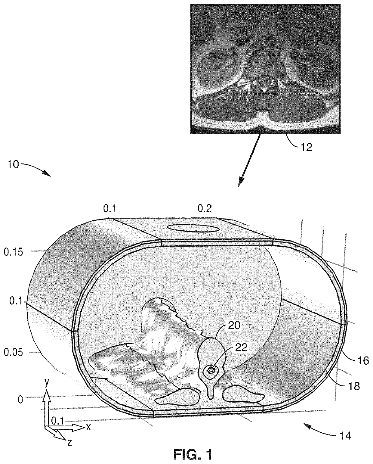
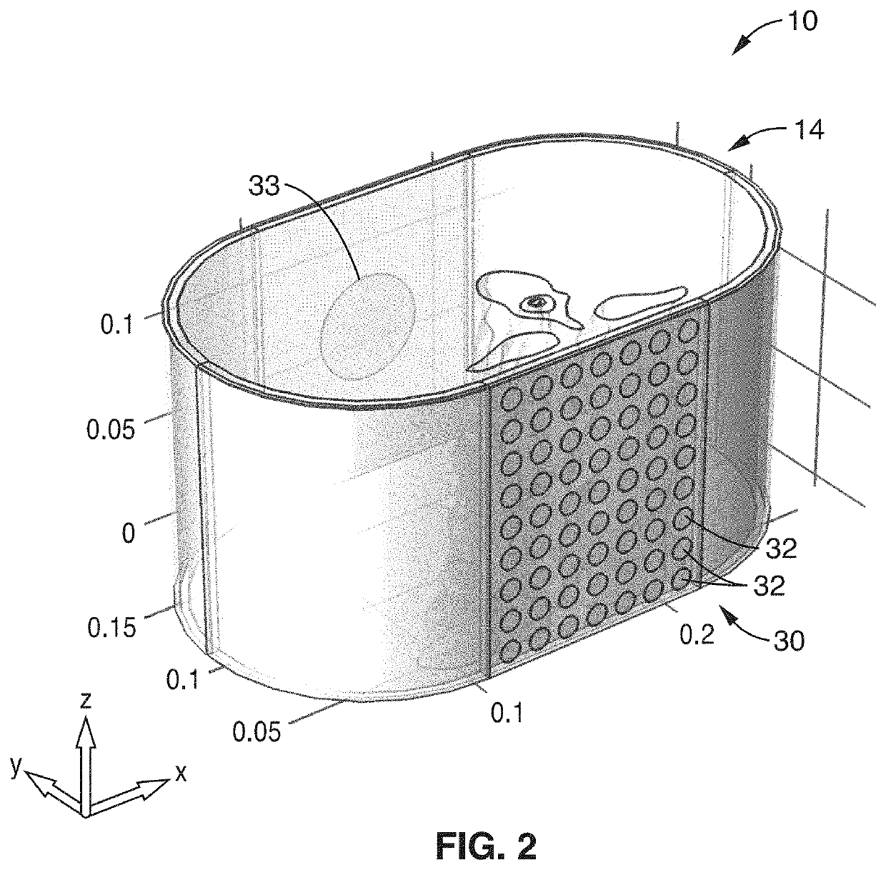
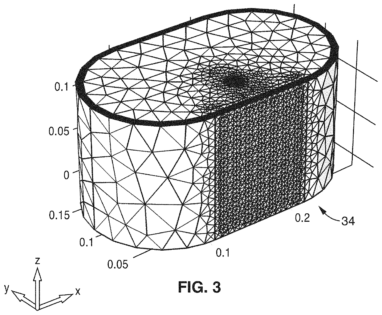
[0047]The key challenges for noninvasive transcutaneous spinal cord stimulation and transcranial current stimulation lie in the ability to provide high spatial and temporal resolution, with a high degree of focal accuracy, while using the correct intensity and directionality using external current injection though an electrode on the skin.

[0048]To accommodate the above mentioned challenges, a multi-electrode system is described below. The multi-electrode system of the present technology includes novel hardware, software, algorithms, and user interface that enable an experiment methodology and development of clinical protocols by (1) a computational 3D model based on MRI / CT data to facilitate the treatment, efficacy, and safety of the device; (2) a novel source localization algorithm to obtain precise target localization and focal precision; (3) optimal stimulation patterns with desired intensity guided by a novel source localization algorithm; (4) miniaturized and fully integrated h...


PUM


Abstract

Methods, apparatus, and systems are disclosed for optimization techniques and a realistic 3D model to design optimal parameters for transcutaneous stimulation to achieve focalized stimulation of a target tissue such as the spinal cord, brain or other internal organ. The methods, apparatus, and systems include generation of a 3D model from a CT / MRI image, as well as an optimization algorithm that enables stimulation of any target location (e.g., on the dorsal root, or on the dorsal column) with any orientation at high precision.

Description

CROSS-REFERENCE TO RELATED APPLICATIONS[0001]This application claims priority to, and is a 35 U.S.C. § 111(a) continuation of, PCT international application number PCT / US2017 / 064970 filed on Dec. 6, 2017, incorporated herein by reference in its entirety, which claims priority to, and the benefit of, U.S. provisional patent application Ser. No. 62 / 532,477 filed on Jul. 14, 2017, incorporated herein by reference in its entirety, and which claims priority to, and the benefit of, U.S. provisional application Ser. No. 62 / 430,490 filed on Dec. 6, 2016, incorporated herein by reference in its entirety. Priority is claimed to each of the foregoing applications.[0002]The above-referenced PCT international application was published as PCT International Publication No. WO 2018 / 106843 on Jun. 14, 2018, which publication is incorporated herein by reference in its entirety.STATEMENT REGARDING FEDERALLY SPONSORED RESEARCH OR DEVELOPMENT[0003]Not ApplicableNOTICE OF MATERIAL SUBJECT TO COPYRIGHT PR...

Claims


Application Information

Patent Timeline
IPC IPC(8): G16H50/50G06F17/50G06F17/11G16H30/40G16H70/20G16H20/40A61N1/08A61B6/03A61B5/055A61B5/00A61N1/36A61B5/0476A61B5/0488A61N1/20
CPCG16H30/40A61B5/4848A61N1/08A61N1/36031A61N1/36014A61B5/0488G16H50/50A61B5/0476G06F17/11G06F17/5018A61B6/032G16H70/20A61N1/36003G06F2217/16G16H20/40A61N1/205A61B5/055A61N1/36007G16H20/30A61B5/721A61B5/743A61B5/0006A61B5/0031A61N1/0476A61N1/36025A61N1/0456G16Z99/00G16H40/60A61B5/316A61B5/374A61B5/378A61B5/291G06F30/23G06F2111/10A61B5/369A61B5/389
Inventor LI, YINGLIU, WENTAILO, YI-KAI
Owner RGT UNIV OF CALIFORNIA
Learn More