
Automatic wire arranging device and automatic wire arranging method applied therein

a wire arranging device and wire arranging technology, applied in the direction of insulated conductors, line/current collector details, cables, etc., can solve the problems of lower and achieve the effect of reducing working hours, saving manpower and reducing the cost of spot soldering the different characteristic core wires of the cabl

Active Publication Date: 2019-11-21
CHENG UEI PRECISION IND CO LTD
View PDF0 Cites 5 Cited by
  • Summary
  • Abstract
  • Description
  • Claims
  • Application Information

AI Technical Summary

Benefits of technology

The automatic wire arranging device described in this patent allows operators to efficiently arrange different color wires in a cable without the need for multiple workers. The device recognizes the different wires through a controller, wire clamping jig, wire arranging rotor, and puncher pin, resulting in faster speeds and lowered defect rates. Additionally, the use of the device reduces the cost of spot soldering the different wires in the cable.

Problems solved by technology

As a result, a cost of spot soldering the different characteristic core wires of the cable is lower.

Method used


Image

  • Automatic wire arranging device and automatic wire arranging method applied therein
  • Automatic wire arranging device and automatic wire arranging method applied therein
  • Automatic wire arranging device and automatic wire arranging method applied therein

Examples


Embodiment Construction

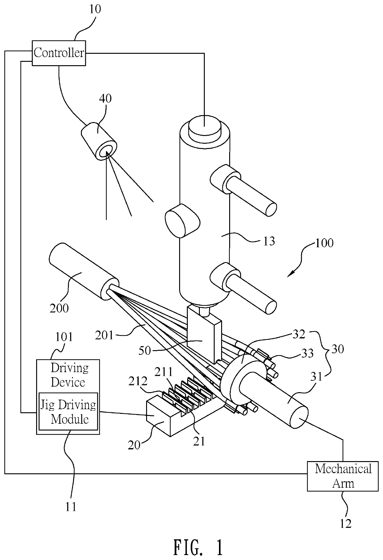
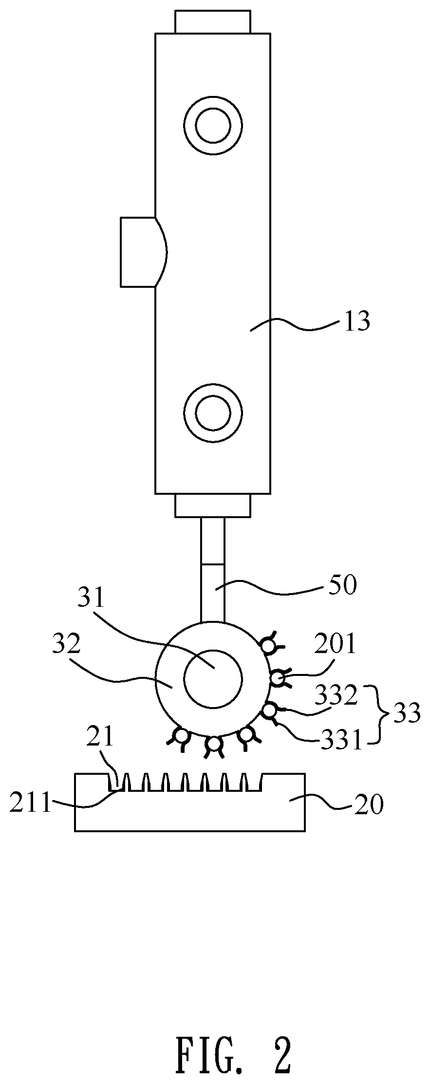
[0014]With reference to FIG. 1, an automatic wire arranging device 100 in accordance with a first preferred embodiment of the present invention is shown. The automatic wire arranging device 100 is used for proceeding automatically arranging a plurality of different characteristic core wires 201 of a cable 200. Each of the plurality of the core wires 201 has different characteristics. The different characteristics of each of the plurality of the core wires 201 include a contour of each of the plurality of the core wires 201, a diameter of each of the plurality of the core wires 201 and color information of each of the plurality of the core wires 201. In the first preferred embodiment, the automatic wire arranging device 100 is used for proceeding automatically arranging a plurality of different-colored core wires 201 of the cable 200. The automatic wire arranging device 100 includes a controller 10, at least one driving device 101, a wire clamping jig 20, a wire arranging rotor 30, a...


PUM


Abstract

An automatic wire arranging device includes a controller, at least one driving device electrically connected with the controller, a wire clamping jig, a wire arranging rotor, at least one charge-coupled device camera and a puncher pin. The wire clamping jig is connected with the at least one driving device. The wire arranging rotor has a spindle, and a cylinder-shaped base portion fastened to a tail end of the spindle. An outer side surface of the base portion is equipped with a plurality of clamping portions. The plurality of the clamping portions are used for clamping a plurality of different characteristic core wires. The wire arranging rotor is connected with the at least one driving device. The at least one charge-coupled device camera faces towards the wire clamping jig and is connected with the controller. The puncher pin is movably disposed above the wire clamping jig.

Description

BACKGROUND OF THE INVENTION1. Field of the Invention[0001]The present invention generally relates to a wire arranging device, and more particularly to an automatic wire arranging device and an automatic wire arranging method applied in the automatic wire arranging device.2. The Related Art[0002]Generally, when a conventional cable having multiple core wires proceed spot soldering, colors of the core wires are all distinguished by eyes of workers, and the core wires are manually placed to corresponding clamping slots of a wire arranging jig according to the colors of the core wires separately, then the core wires are spot soldered one by one. However, because the workers are easily tired and distinguish the colors wrongly, the core wires are pressed into wrong positions and the wrongly soldered core wires are increased to make rates of repairing and even scrapping the core wires high. In addition, in a process of arranging the core wires, more workers are needed and working hours are...

Claims


Application Information

Patent Timeline
IPC IPC(8): H01R43/02H01B13/00
CPCH01B7/363H01B7/361H01R43/0263H01B13/0036H01R43/28
Inventor LO, SHENG CHIEH
Owner CHENG UEI PRECISION IND CO LTD
Learn More