Automatic step steel plate cutting and welding device, and method thereof

a step steel plate and welding device technology, applied in welding apparatus, metal-working equipment, manufacturing tools, etc., can solve the problems of increasing the cost of steel plate manufacturing, and relatively long whole production time, so as to improve production efficiency, save manpower, and save production time

Active Publication Date: 2019-11-28
KUNSHAN THETA MICRO
View PDF2 Cites 31 Cited by
  • Summary
  • Abstract
  • Description
  • Claims
  • Application Information

AI Technical Summary

Benefits of technology

[0004]In view of the above, the present invention provides a fully-automatic cutting and welding apparatus and method for stepped steel plate. A stepped steel plate is manufactured in a laser cutting and welding manner, to resolve an environment pollution problem from a source, and a manufacturing process of laser-cutting and welding the steel plate is much simpler than an etching and electroforming process, thereby greatly saving a production time. In addition, a device in this application differs from a conventional steel plate cutting or welding machine. The conventional cutting or welding machine can complete only one operation, while cutting and welding functions are integrated in the fully-automatic cutting and welding apparatus for stepped steel plate of this application, and a whole process of manufacturing a steel plate step part is a fully-automatic operation, thereby greatly improving production efficiency while saving manpower.

Problems solved by technology

However, because the etching or electroforming process causes great pollution to an environment due to itself, it is quite a headache to manufacturers.
The environment pollution problem greatly increases costs of manufacturing of steel plates.
In addition, a complex process of the etching or electroforming process also makes a whole production time relatively long, reduces production efficiency, and cannot satisfy demands for production and requirements on environmental protection to the maximum degree.

Method used


Image

  • Automatic step steel plate cutting and welding device, and method thereof
  • Automatic step steel plate cutting and welding device, and method thereof
  • Automatic step steel plate cutting and welding device, and method thereof

Examples


Embodiment Construction

[0068]The following describes embodiments of the present invention in detail. Examples of the embodiments are shown in the accompanying drawings, and numerals that are the same or similar throughout represent the same or similar elements or elements having the same or similar functions. The following embodiments described with reference to the accompanying drawings are exemplary, are merely used to explain the present invention, and should not be construed as a limitation to the present invention.

[0069]In description of the present invention, it should be understood that orientation or position relationships indicated by terms “up”, “down”, “bottom”, “top”, “front”, “rear”, “inside”, “outside”, “horizontal”, “vertical”, or the like are orientation or position relationships shown based on the accompanying drawings, are only for the purpose of describing the present invention and simplifying the description, do not indicate or imply that indicated apparatuses or elements necessarily h...


PUM

PropertyMeasurementUnit
distancesaaaaaaaaaa
pressureaaaaaaaaaa
adsorptionaaaaaaaaaa

Abstract

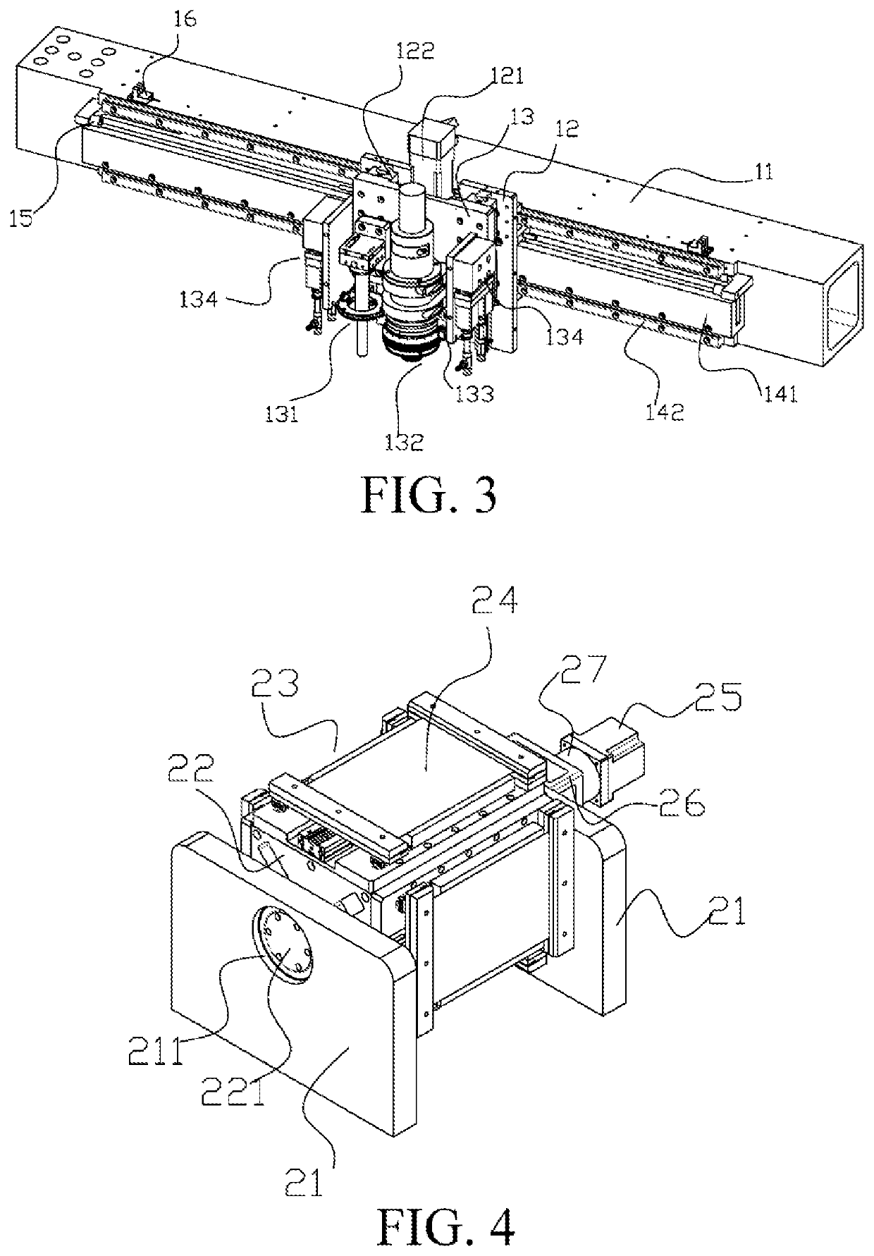
A fully-automatic cutting and welding apparatus for stepped steel plate, comprising a multi-function motion module (1), an automatic feed library turntable (2), a product flip platform (3), a steel plate bearing module (4), a pedestal (5), and a base (6). The multi-function motion module (1) is capable of performing motion in a Y-axis direction on the pedestal (5); the pedestal (5) is fixed on a surface edge of the base (6);the automatic feed library turntable (2) is fixed at one end of the base (6); the product flip platform (3) is disposed between the automatic feed library turntable (2) and the steel plate bearing module (4), and the steel plate bearing module (4) is fixed at the other end of the base (6) for bearing and fixing a steel plate, and is used as a welding platform for the final steel plate step part.

Description

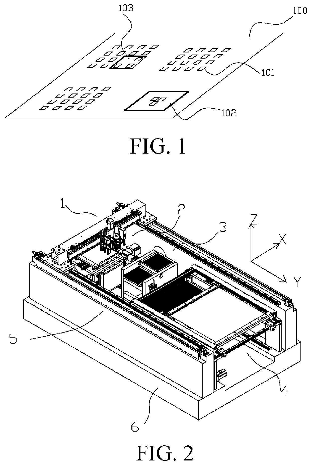
BACKGROUND OF THE PRESENT INVENTIONField of Invention[0001]The present invention belongs to the SMT field, and specifically, relates to a fully-automatic cutting and welding integrated apparatus and method for stepped steel plate.Description of Related Arts[0002]In the SMT industry, electronic components with different specifications need different solder paste amounts when being welded onto a circuit board. When electronic components with different specifications appear on the same surface of the circuit board, to accurately control the solder paste amounts to obtain good welding quality, solder pastes with different thicknesses need to be printed on the same surface of the circuit board. Therefore, a so-called locally thickening and locally thinning stepped special template, such as an SMT steel plate (100) with a pattern opening (101) shown in FIG. 1, appears accordingly. A local area of the steel plate (100) needs to be thickened or thinned according to requirements of printing ...

Claims


Application Information

Patent Timeline
Patent Type & Authority Applications(United States)
IPC IPC(8): B23K26/08B23K26/046B23K26/24B23K26/38
CPCB23K26/08B23K26/38B23K26/046B23K26/24B23K26/032B23K26/0884
Inventor WEI, ZHILINGNING, JUNYANG, ZHAOWENWANG, WUHUAIXUE, HAIJUN
Owner KUNSHAN THETA MICRO
Why Eureka
Try Eureka