Electronic switch control circuits for solar lighting systems and methods for controlling the same

Active Publication Date: 2019-11-28
WU HAO
View PDF0 Cites 0 Cited by
  • Summary
  • Abstract
  • Description
  • Claims
  • Application Information

AI Technical Summary

Benefits of technology

The patent text describes an electronic switch control circuit for solar lighting systems that can replace the mechanical switch without adding extra costs. The circuit improves reliability and stability of the solar LED lighting products by solving leakage issues and avoiding the use of a conventional mechanical switch. The electronic switch with the control circuit meets waterproof and moisture-proof requirements, can pass through waterproof tests under 360-degree spraying, and reduces processing volume and costs. The integrated electronic switch also has improved productivity and reduces labor costs.

Problems solved by technology

If a mechanical switch is used to isolate the batteries from the discharge circuits in the solar LED lighting products, completely sealing of the solar LED lighting products cannot be achieved and thus water-proof and moisture-proof of the solar LED lighting products with the mechanical switch cannot be achieved.
Oxidation and short circuit and the like are primary causes leading to decreased service life of the solar LED lighting products.
Additionally, use of the mechanical switch in the solar LED lighting products may undesirably influence appearance of the products and lead to additional cost for sealing.
And, the sealing effect is unsatisfied.

Method used


Image

  • Electronic switch control circuits for solar lighting systems and methods for controlling the same
  • Electronic switch control circuits for solar lighting systems and methods for controlling the same
  • Electronic switch control circuits for solar lighting systems and methods for controlling the same

Examples


first embodiment

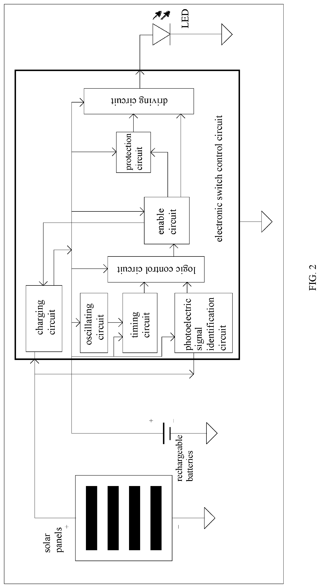
[0038]FIGS. 2 and 7 illustrate the first embodiment as provided herein.

[0039]As shown in FIG. 2, the solar panels of the solar lighting system are respectively coupled to a charging circuit and a photoelectric signal identification circuit that is coupled to a logic control circuit and an enable circuit sequentially. The enable circuit is respectively coupled to a driving circuit and the charging circuit that is coupled to the common end of the driving circuit and rechargeable batteries. The common end of the driving circuit and the rechargeable batteries is also coupled to an oscillating circuit, a timing circuit, the photoelectric signal identification circuit, the logic control circuit, the enable circuit and a protection circuit. The oscillating circuit is coupled to the timing circuit that is coupled to the logic control circuit. The enable circuit is coupled to the protection circuit which is coupled to the driving circuit. The driving circuit is coupled to a LED lamp. The osc...

second embodiment

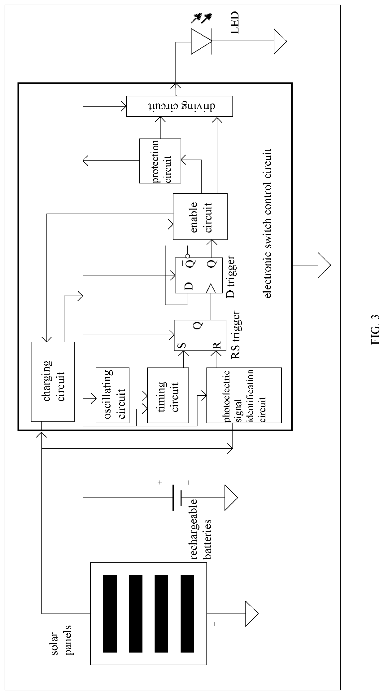
[0047]FIGS. 3 and 8 illustrate the second embodiment as provided herein.

[0048]As shown in FIG. 3, the solar panels of the solar lighting system are respectively coupled to a charging circuit and a photoelectric signal identification circuit which is coupled to a RS trigger, a D trigger, an enable circuit and a driving circuit sequentially. The enable circuit is respectively coupled to a protection circuit coupled to the driving circuit and the charging circuit coupled to the common end of the driving circuit and the rechargeable batteries. The common end of the driving circuit and the rechargeable batteries is also coupled to an oscillating circuit, a timing circuit, the photoelectric signal identification circuit, the RS trigger, the D trigger, the enable circuit, the protection circuit and the driving circuit. The oscillating circuit is coupled to the timing circuit that is coupled to the RS trigger. Q pin of the D trigger is coupled to D pin of the D trigger. The driving circuit ...

third embodiment

[0056]FIG. 4 illustrates the third embodiment as provided herein.

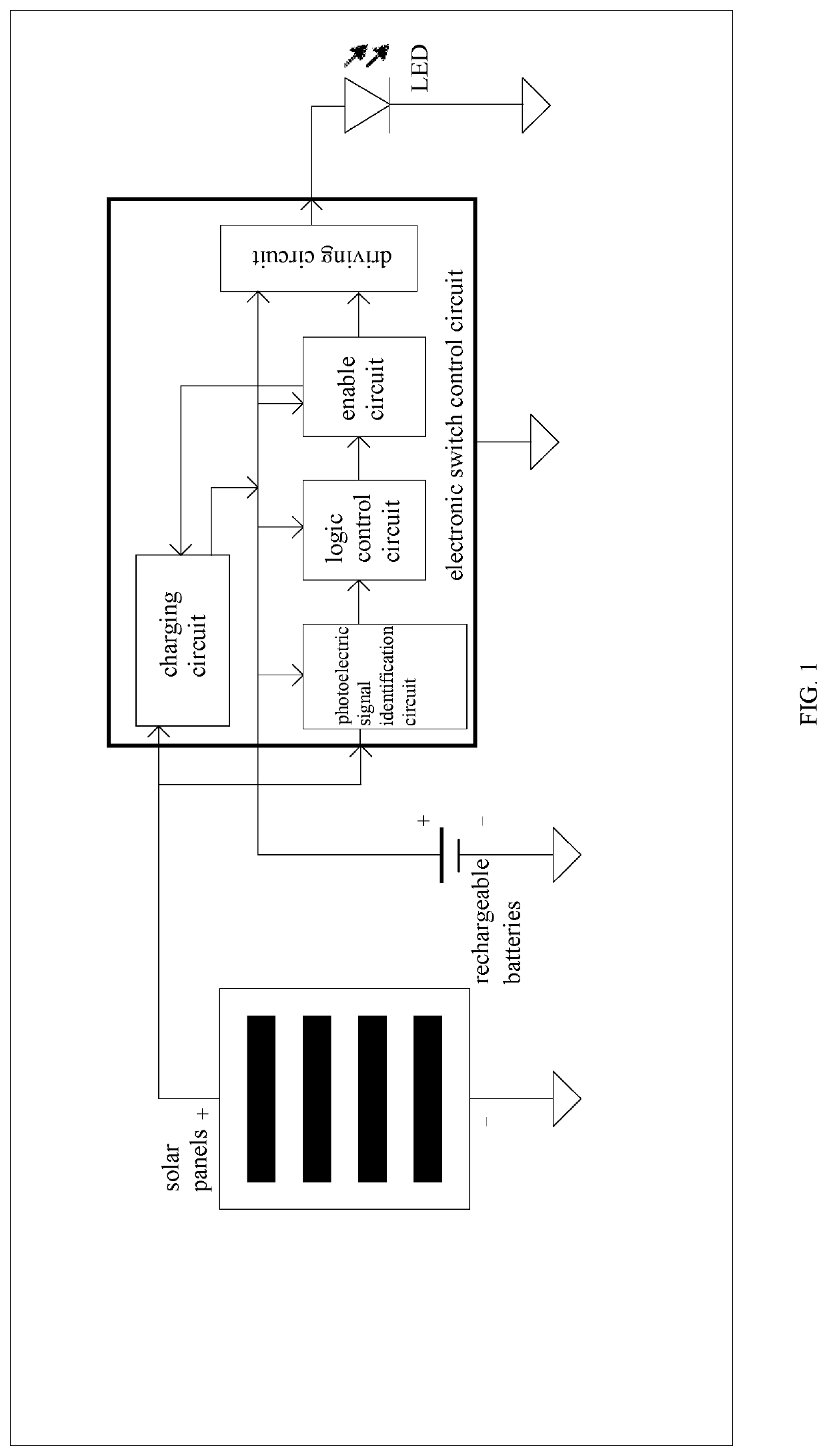
[0057]As shown in FIG. 4, the solar light system as provided herein comprises solar panels which are coupled to a charging circuit. Rechargeable batteries are coupled to a driving circuit, and the charging circuit is respectively coupled to a photoelectric signal identification circuit, an enable circuit, the common end of the rechargeable batteries and a driving circuit. The common end of the rechargeable batteries and the driving circuit is respectively coupled to the photoelectric signal identification circuit, the logic control circuit and the enable circuit. The photoelectric signal identification circuit is coupled to the logic control circuit, the enable circuit, the driving circuit, and the LED lamp sequentially.


PUM


Abstract

An electronic switch control circuit for a solar lighting system and a method for controlling the same. Solar panels of the solar lighting system are respectively coupled to a charging circuit and a photoelectric signal identification circuit which is coupled to a logic control circuit and an enable circuit sequentially. The enable circuit is respectively coupled to a driving circuit and the charging circuit. The photoelectric signal identification circuit, the logic control circuit, the enable circuit and the charging circuit are respectively coupled to the common end of the driving circuit and rechargeable batteries. The electronic switch control circuit further includes a timing circuit and an oscillating circuit, wherein the oscillation circuit is coupled to the timing circuit, and the timing circuit is coupled to the logic circuit. The oscillation circuit and the timing circuit are coupled to the common end of the rechargeable batteries and the driving circuit.

Description

CROSS REFERENCE TO RELATED APPLICATIONS[0001]The present application is a Continuation Application of PCT Application No. PCT / CN2017 / 090086 filed on Jun. 26, 2017, the contents of which are incorporated herein by reference in their entirety.FIELD OF THE INVENTION[0002]The present invention relates to electrical technology, more particular, to an electronic switch control circuit for a solar lighting system and a method for controlling the same.BACKGROUND OF THE INVENTION[0003]At present, in order to solve electric leakage problem occurring in circuit boards of solar LED lighting products with rechargeable batteries during transportation (by sea) and storage (sometimes up to one year), a mechanical switch (an insulation sheet) is provided to isolate the batteries from discharge circuits, thereby maintaining battery power of the products and avoiding excessive leakage during long-term storage and transportation. As such, the products will maintain sufficient battery power for customer...

Claims


Application Information

Patent Timeline
IPC IPC(8): H05B37/02H02J7/35H02J7/00H05B33/08H05B44/00
CPCH02J7/0013H05B37/0281H02J7/35H05B33/0842H05B47/16H05B45/00Y02E10/50Y02E70/30H02S40/38F21S9/03
Inventor WULI, WEIHUA
Owner WU HAO
Why Eureka
Try Eureka