

Precast tub
a precast tub and hot tub technology, applied in the field of hot tubs and swimming pools, can solve the problems of general durability limitation, inability to meet the needs of economical refurbishment, and lack of structural strength, so as to reduce the time of site construction, facilitate transportation and delivery, and reduce weight
- Summary
- Abstract
- Description
- Claims
- Application Information
AI Technical Summary
Benefits of technology
Problems solved by technology
Method used
Image

Examples
Embodiment Construction
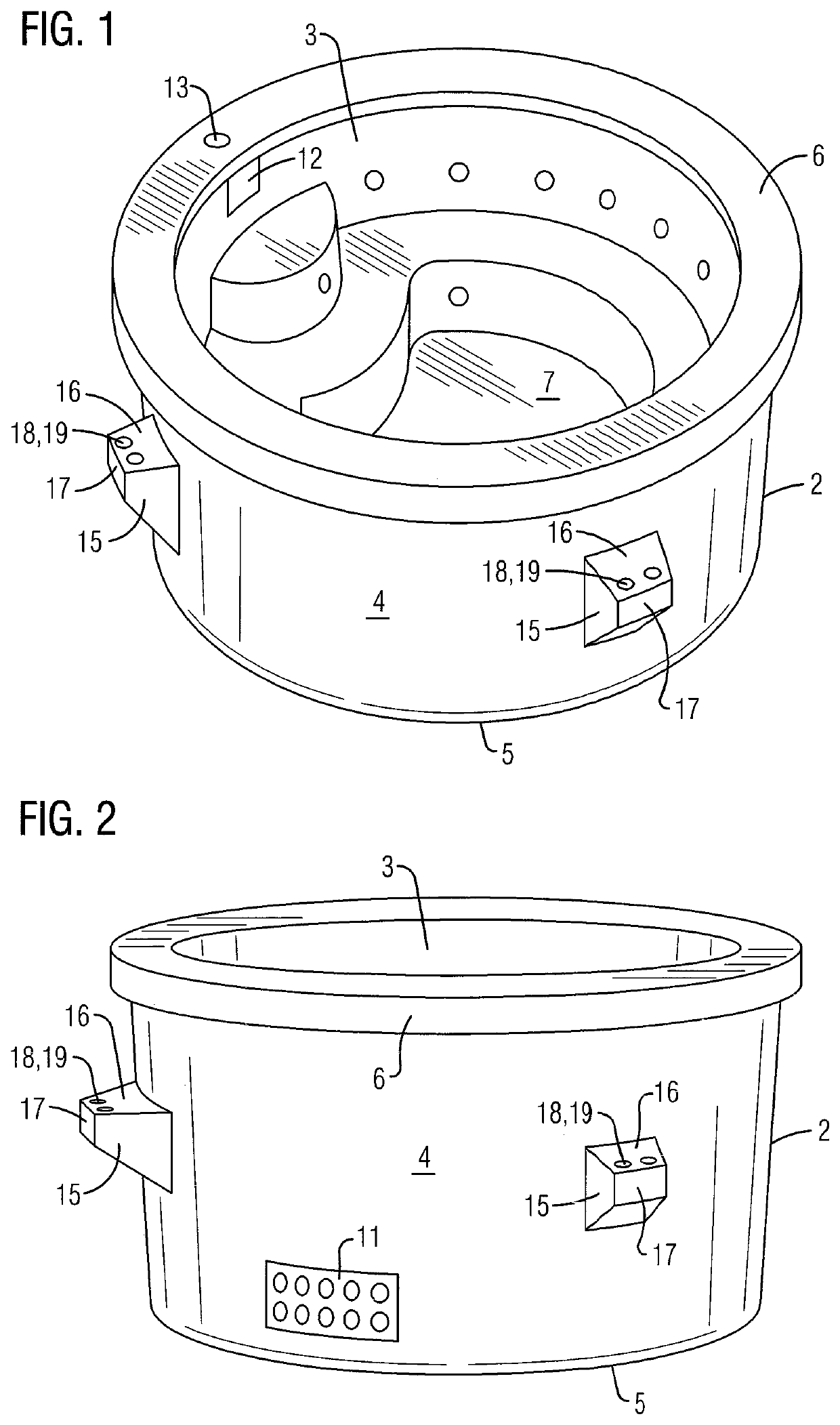
[0044]For purposes of describing the preferred embodiment, the terminology used in reference to the numbered accessories in the drawings is as follows:
[0045]1. precast tub, generally
[0046]2. perimeter side wall
[0047]3. interior surface of perimeter side wall
[0048]4. exterior surface of perimeter side wall
[0049]5. bottom edge of perimeter side wall
[0050]6. top edge of perimeter side wall
[0051]7. floor
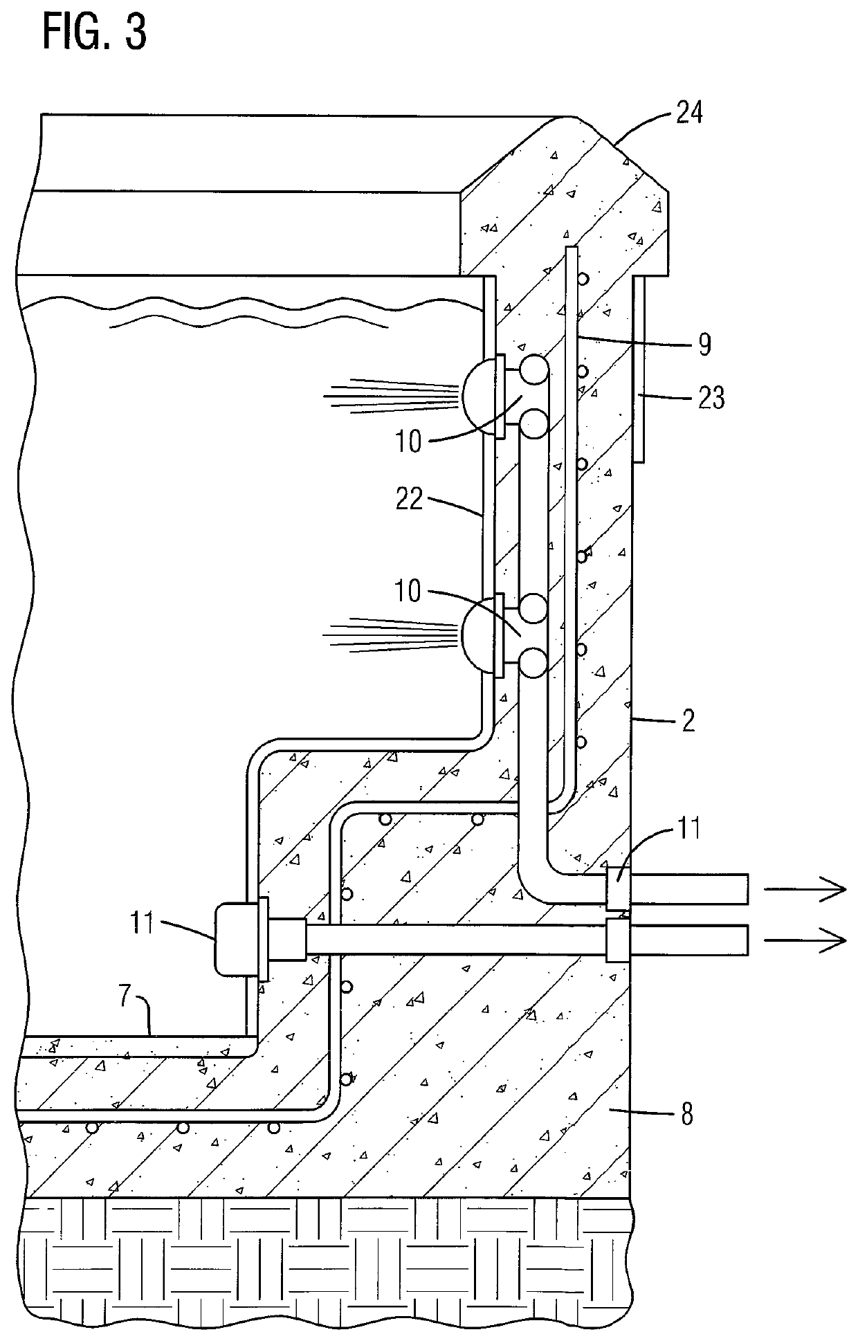
[0052]8. concrete
[0053]9. reinforcing steel
[0054]10. plumbing system
[0055]11. electrical system
[0056]12. skimmer
[0057]13. skimmer access
[0058]14. manifold
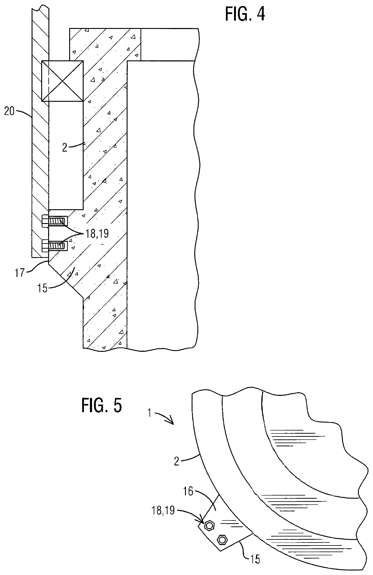
[0059]15. support bracket
[0060]16. a top perpendicular support surface
[0061]17. side parallel support surface
[0062]18. attachment means
[0063]19. embedded nut
[0064]20. hoisting bracket
[0065]21. auxiliary structure
[0066]22. interior finish
[0067]23. exterior finish
[0068]24. coping
[0069]With reference to FIG. 1-7, a precast tub 1 of the present invention is illustrated. The precast tub 1 of the present invention comprises at least one perim...
PUM
 Abstract
Description
Claims
Application Information