
Precast tub

a precast tub and hot tub technology, applied in the field of hot tubs and swimming pools, can solve the problems of general durability limitation, inability to meet the needs of economical refurbishment, and lack of structural strength, so as to reduce the time of site construction, facilitate transportation and delivery, and reduce weight

Active Publication Date: 2019-11-19
SELINGER GREGORY M
View PDF9 Cites 5 Cited by
  • Summary
  • Abstract
  • Description
  • Claims
  • Application Information

AI Technical Summary

Benefits of technology

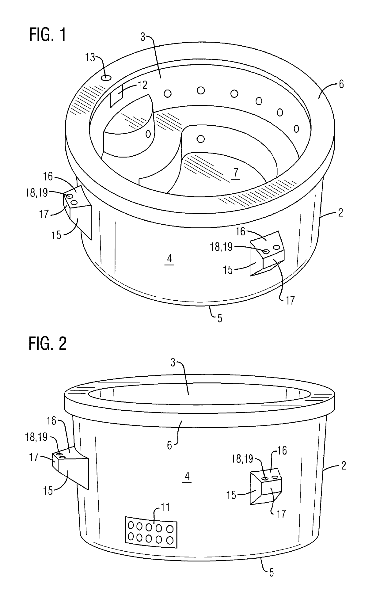
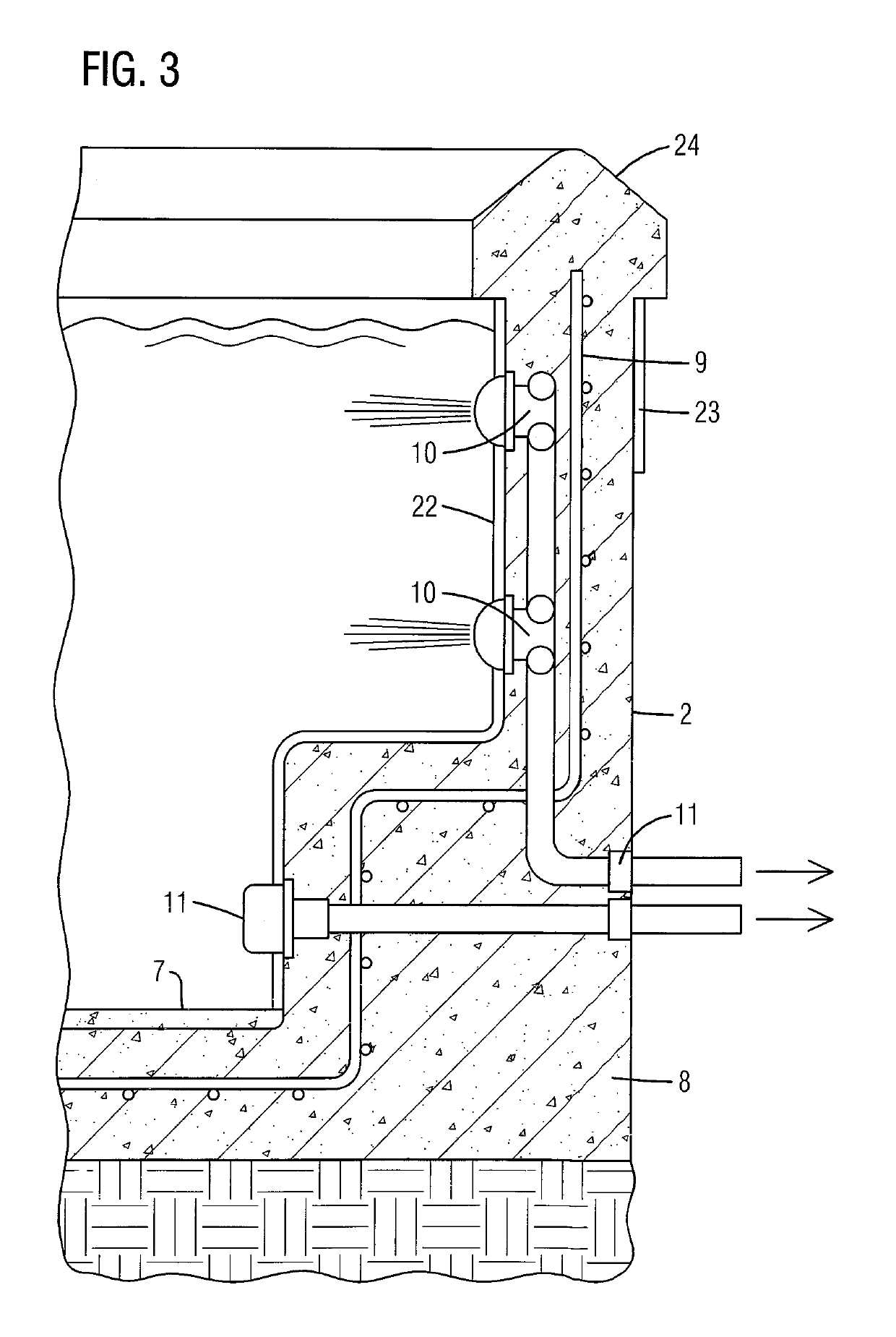
The present invention provides a precast concrete tub that has no exposed pipes or fittings on the exterior of the structure, which protects the piping and componentry from damage caused by transport and ground conditions after installation including frost heave. The tub may be cast using various shaped molds to create circular or rectangular tube that can be used for various purposes like hot tubs, swim spas, swimming pools, and so forth. The interior of the tub has a fully encased plumbing system for circulation and jets and electrical systems. The tub can be easily hoisted and can provide attachment points for building auxiliary structures around it.

Problems solved by technology

These tubs typically utilize small electric pumps, filters and heaters due to size constraints.
They are generally limited in durability and are considered depreciable components akin to other outdoor consumer products such as barbecues, patio furniture and so forth.
The interior finishes do not lend themselves to economical refurbishment.
Such tubs offer no structural strength and thus cannot support any auxiliary structures, perimeter decking and so forth.
Conventional tubs also cannot be customized beyond a limited selection of interior finish colors.
They are also typically limited in depth and perimeter size.
They are generally designed to be easily installed without heavy equipment so a tub that is too wide or heavy would be cumbersome and be difficult to install.
Further, there are severe limitations on the capabilities of the self-contained heating and filtration systems which necessitates a limited water volume.
There are some larger self-contained swim spa hybrids available but they too utilize the same construction techniques and suffer from limited durability, structural integrity and so forth and thus, are also considered a depreciating consumable product.
There are a few other types of tubs available using other materials such as wood, or vinyl over prefabricated steel but they suffer from many of the aforementioned limitations and comprise a tiny fraction of the spa market.
These finishes also offer unparalleled durability if installed correctly.
However, concrete tubs fabricated and poured on site have their own set of limitations.
One limitation stems from the fact that only a small percentage of the market is serviced by a capable concrete contractor.
Because the work is all done on site, if a customer is not within close proximity to a reputable concrete swimming pool builder, he or she is out of luck.
It is not economical for the builder to travel a long distance to construct the tub as it requires many small processes spread over several weeks.
Even if the client has a geographically proximate contractor the builder may lack the technical knowledge to construct the product properly.
There are very few building standards in this industry which results in widely disparate product quality.
Assuming that the client can locate a reputable and capable contractor, limitations are caused by the fact that the work will take place on site over a period of several weeks.
This is because the construction of the product is quite complex and requires many separate stages, often involving curing time in between steps.
This work is, of course, weather permitting, which limits the number of working days, especially in colder climates.
The weather can also impact the product quality severely resulting in unacceptable variation.
As mentioned above, there is almost no standardization in the industry, which results in low product consistency.
There is also the inconvenience and increased cost of a large construction site over a fairly long period of time.
For these reasons, the concrete tub has enjoyed fairly limited traction in the marketplace.
Although almost any concrete tub is superior to any preformed fiberglass tub, they are generally plagued by high cost, inconvenience, variable product quality and limited availability.

Method used


Image

  • Precast tub
  • Precast tub
  • Precast tub

Examples


Embodiment Construction

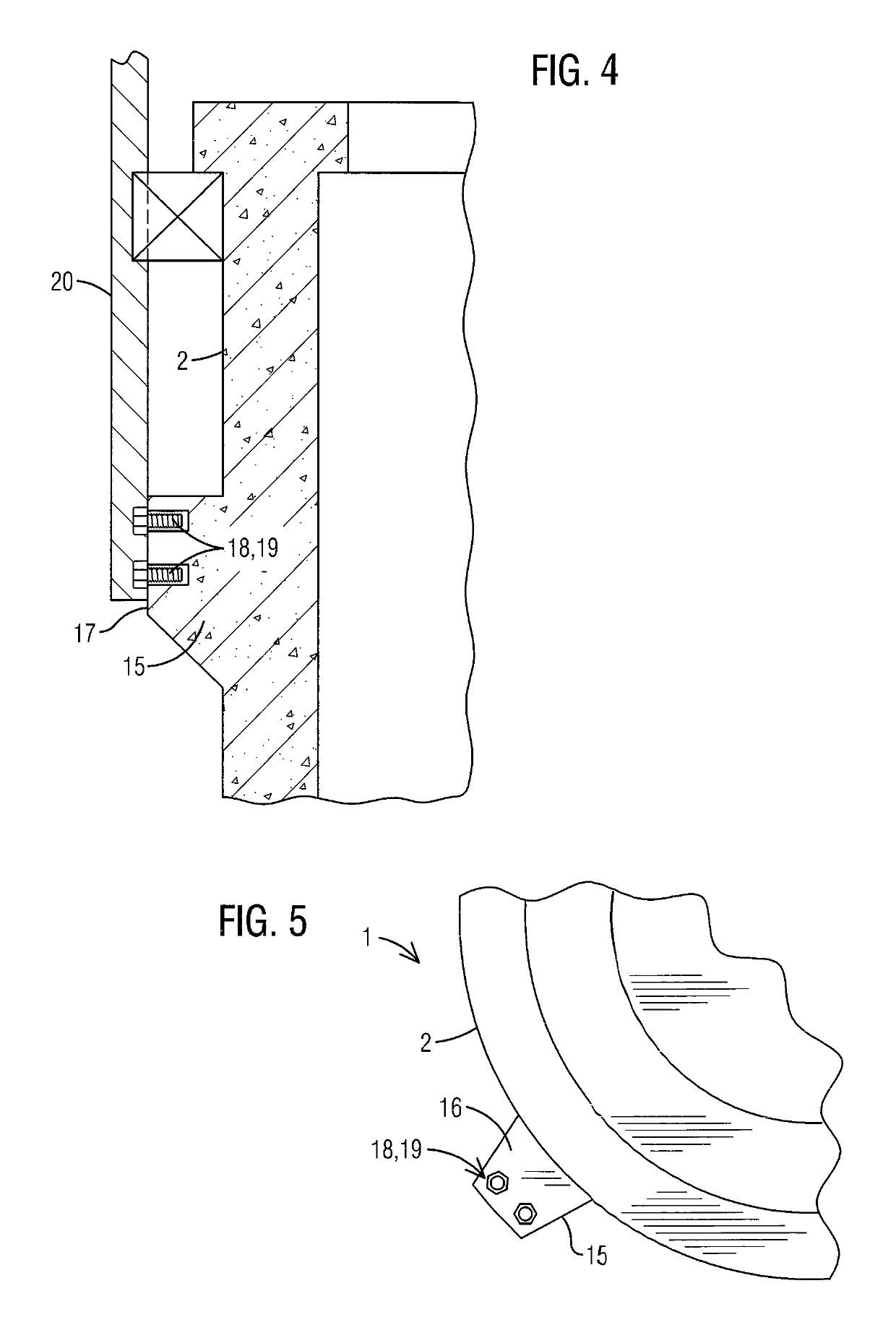
[0044]For purposes of describing the preferred embodiment, the terminology used in reference to the numbered accessories in the drawings is as follows:[0045]1. precast tub, generally[0046]2. perimeter side wall[0047]3. interior surface of perimeter side wall[0048]4. exterior surface of perimeter side wall[0049]5. bottom edge of perimeter side wall[0050]6. top edge of perimeter side wall[0051]7. floor[0052]8. concrete[0053]9. reinforcing steel[0054]10. plumbing system[0055]11. electrical system[0056]12. skimmer[0057]13. skimmer access[0058]14. manifold[0059]15. support bracket[0060]16. a top perpendicular support surface[0061]17. side parallel support surface[0062]18. attachment means[0063]19. embedded nut[0064]20. hoisting bracket[0065]21. auxiliary structure[0066]22. interior finish[0067]23. exterior finish[0068]24. coping

[0069]With reference to FIG. 1-7, a precast tub 1 of the present invention is illustrated. The precast tub 1 of the present invention comprises at least one perim...


PUM


Abstract

A single unit precast concrete tub (1) formed out of concrete wherein a plumbing system (10) and electrical system (11) are encased within preformed concrete walls. The fully encased plumbing system protects the pipes against damage and frost. Support brackets (15) are formed on an exterior surface (4) of the side wall (2) to provide attachment points for hoisting the precast tub for transportation and installation. The support brackets also provide attachment points for building auxiliary structures, such as decks, around the precast tub.

Description

FIELD OF THE INVENTION[0001]This invention relates to hot tubs and swimming pools and more particularly a hot tub or swim spa precast from concrete having a structure that allows the tub to be constructed entirely off-site and then to be transported and installed on-site.BACKGROUND OF THE INVENTION[0002]The hot tub industry is dominated by fiberglass shell hot tubs. These are typically self-contained units with all of the piping and associated equipment (pumps, filter, heater and so forth) attached to the outside of a thin fiberglass shell. Such tubs are designed to rest on a concrete slab above ground and require an exterior skirt to conceal the piping and mechanical equipment. They may include a set of wooden steps for entry and exit. These tubs typically utilize small electric pumps, filters and heaters due to size constraints.[0003]There are some fiberglass tubs that are designed to drop into the ground, typically adjacent to swimming pools. These tubs utilize similar constructi...

Claims


Application Information

Patent Timeline
Patent Type & Authority Patents(United States)
IPC IPC(8): E04H4/00A61H33/00
CPCA61H33/6068E04H4/0093A61H33/6005E04H4/0075A61H1/00E04H4/0037
Inventor SELINGER, GREGORY M.
Owner SELINGER GREGORY M
Learn More