Vehicle controller

a technology for controllers and vehicles, applied in the direction of engines, machines/engines, propulsion using engine-driven generators, etc., can solve the problems of inability to control the amount of heat generated by heaters, inability to control the supply of battery power, and excessive temperature increase, so as to reduce the egr ratio, increase the amount of urea solution, and increase the concentration of nox in exhaust gas

Active Publication Date: 2019-12-05
TOYOTA JIDOSHA KK
View PDF0 Cites 2 Cited by
  • Summary
  • Abstract
  • Description
  • Claims
  • Application Information

AI Technical Summary

Benefits of technology

[0018]In the above-described configuration, when it is determined that an anomaly has occurred in the driving circuit, the concentration of NOx in exhaust gas is increased by reducing the EGR ratio. This increases the amount of urea solution in which NOx should be reduced in the catalyst. Thus, the amount increasing process is e

Problems solved by technology

In this case, the EHC and a member located proximate to the EHC, such as the catalyst, may excessively increase in temperature.
When an anomaly where power is constantly supplied from the battery to the heater has occurred in the driving circuit, the supply of power from the battery cannot be controlled.
Thus, the amount of heat generated by the heater may not be able to be controlled.
Consequently, this may excessively increase the temperature in the member located proximate to the heater such as the catalyst, which is subject to heating.
Thus, in the above-described configuration, when an anomaly has occurred in the driving circuit, the electrical path between the battery and the heater is broken.
This prevents the constant supply of electric power from the battery to the heater.
Thus, as compared to when the electrical path is not broken, an excessive increase is limited in the temperature of the member located proximate to the heater.
However, when the e

Method used


Image

  • Vehicle controller
  • Vehicle controller
  • Vehicle controller

Examples


first embodiment

[0029]A vehicle controller 80 according to a first embodiment will now be described with reference to the drawings.

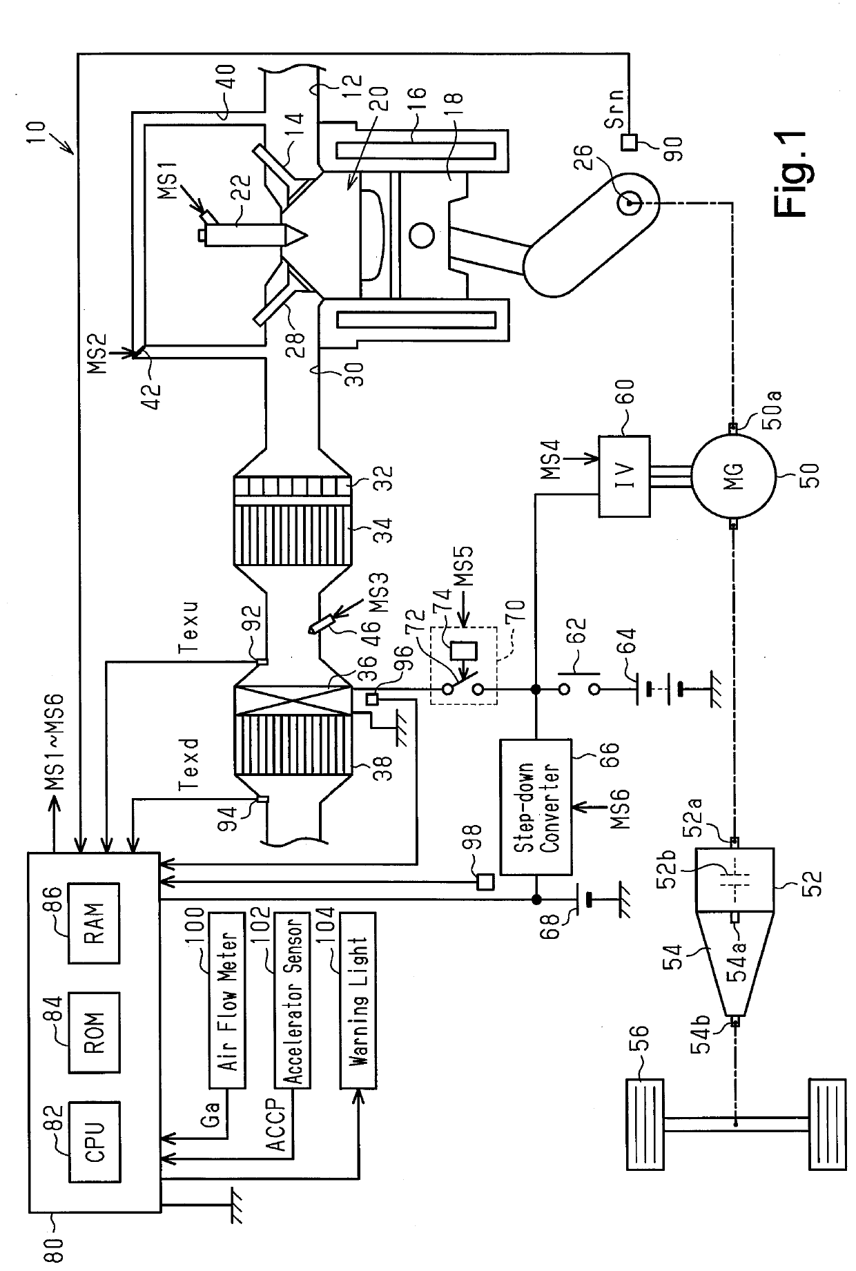
[0030]In an internal combustion engine 10 shown in FIG. 1, air drawn from an intake passage 12 flows, as an intake valve 14 opens, into a combustion chamber 20 defined by a cylinder 16 and a piston 18. Fuel such as diesel fuel is injected into the combustion chamber 20 from a fuel injection valve 22. A mixture of air and fuel in the combustion chamber 20 is ignited and burned when compressed. The energy generated by the combustion of the air-fuel mixture is converted into rotational energy of a crankshaft 26 by the piston 18. The burned mixture is discharged as an exhaust gas into an exhaust passage 30 as an exhaust valve 28 opens. The exhaust passage 30 includes an oxidation catalyst 32 and a diesel particulate filter (DPF) 34 for collecting particulate matter arranged at the downstream side of the oxidation catalyst 32. The exhaust passage 30 also includes a heater, n...

second embodiment

[0059]The second embodiment will now be described with reference to the drawings, focusing on the difference from the first embodiment.

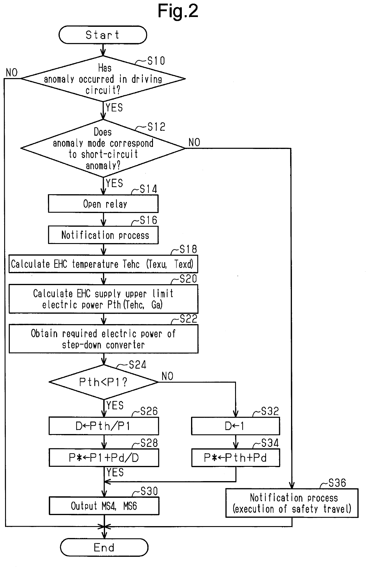
[0060]In the first embodiment, when the intake air amount Ga is small, the EHC supply upper limit electric power Pth has a small value. Thus, the duty cycle D needs to be small. This may make it difficult to set the electric power supplied to the step-down converter 66 to the required electric power Pd because of the limitation of a rated current of the step-down converter 66 and a rated current of the motor generator 50.

[0061]In the present embodiment, a lock-up clutch 52b is operated in addition to the processes shown in FIG. 2 to execute processes for maximizing the intake air amount Ga.

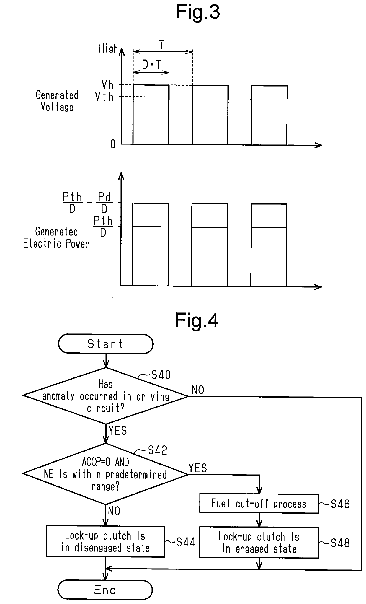
[0062]FIG. 4 illustrates a procedure for the processes. The processes illustrated in FIG. 4 are implemented when the CPU 82 repeatedly executes the program stored in the ROM 84, for example, in a predetermined cycle.

[0063]In a series of processes shown in FIG. 4, t...

third embodiment

[0069]The third embodiment will now be described with reference to the drawings, focusing on the difference from the first embodiment.

[0070]In the first and second embodiments, the idling process is executed when the accelerator operation amount ACCP is zero. During this process, since the rotational speed NE is small, the intake air amount Ga is small. As a result, the duty cycle D needs to be small. This may make it difficult to supply the required electric power Pd of the step-down converter 66.

[0071]In the present embodiment, the following processes are executed in addition to the processes of FIG. 2.

[0072]FIG. 5 illustrates a procedure for the processes executed by the vehicle controller 80. The processes illustrated in FIG. 5 are implemented when the CPU 82 repeatedly executes the program stored in the ROM 84, for example, in a predetermined cycle.

[0073]In a series of processes shown in FIG. 5, the CPU 82 first determines whether the condition of executing the idling process h...


PUM


Abstract

A vehicle controller is configured to execute a duty cycle control process of alternately repeating an electric power generation execution period and an electric power generation stop period of an electric generator and controlling a duty cycle, which is a ratio of the electric power generation execution period to a single cycle of repeated cycles, when determining that an anomaly has occurred in a driving circuit. The duty cycle control process includes at least one of two processes, a process of setting the duty cycle to be larger when a member in an overheatable region, in which overheating is possibly performed by the heater, has a low temperature than when the member has a high temperature and a process of setting the duty cycle to be larger when an internal combustion engine has a large intake air amount than when the engine has a small intake air amount.

Description

BACKGROUND1. Field[0001]The following description relates to a vehicle controller configured to control a vehicle that includes an internal combustion engine capable of transmitting rotational power of a crankshaft to a driven wheel, a catalyst arranged in an exhaust passage of the internal combustion engine, a heater that generates heat by consuming electric power with the catalyst as a subject to be heated, a driving circuit that supplies the heater with electric power of a battery, and an electric generator that converts the rotational power of the crankshaft into electric power and supplies the driving circuit with the electric power.2. Description of Related Art[0002]Japanese Laid-Open Patent Publication No. 2009-227038 discloses an example of a vehicle including a controller. In the electric power generated by the motor generator, the controller controls the amount of electric power supplied to a heater that heats a catalyst (electrically heated catalyst: EHC).[0003]When an an...

Claims


Application Information

Patent Timeline
IPC IPC(8): B60K6/26B60K6/24B60K6/28B60L50/16
CPCB60L2240/421B60K6/26F02M2026/005B60K6/28B60K6/24B60L50/16F01N3/2013F01N9/00F01N11/00F02B63/04F02D29/06F02D41/0077F01N3/208F01N2240/16F02D2021/083F01N2610/02F01N2610/14B60L2210/12B60L1/02B60L3/04B60L3/0046B60L58/14B60K6/48B60K2006/4825B60W20/50B60W2510/0628B60W2510/068B60W2540/10B60W2710/0644B60W2710/0627B60W10/06B60W10/08B60W10/30F01N2550/22F01N3/00Y02T10/12Y02T10/40Y02T10/62Y02T10/72Y02T10/70Y02T10/7072Y02A50/20
Inventor TSUCHIYAMA, MAKIO
Owner TOYOTA JIDOSHA KK
Why Eureka
Try Eureka