Electric brake system

a technology of electric brakes and brake pedals, applied in the direction of brake systems, vehicle sub-unit features, braking components, etc., can solve the problem of requiring a significant brake pedal force from the driver, and achieve the effect of effective emergency braking

Active Publication Date: 2019-12-05
HL MANDO CORP
View PDF0 Cites 16 Cited by
  • Summary
  • Abstract
  • Description
  • Claims
  • Application Information

AI Technical Summary

Benefits of technology

[0008]It is an aspect of the present disclosure to provide an electronic brake system capable of more effectively performing emergency braking in the event of a system abnormality.

Problems solved by technology

However, in the conventional brake system, the fallback mode relies on the driver's brake pedal operation, requiring a significant brake pedal force from the driver.

Method used


Image

  • Electric brake system
  • Electric brake system
  • Electric brake system

Examples


first embodiment

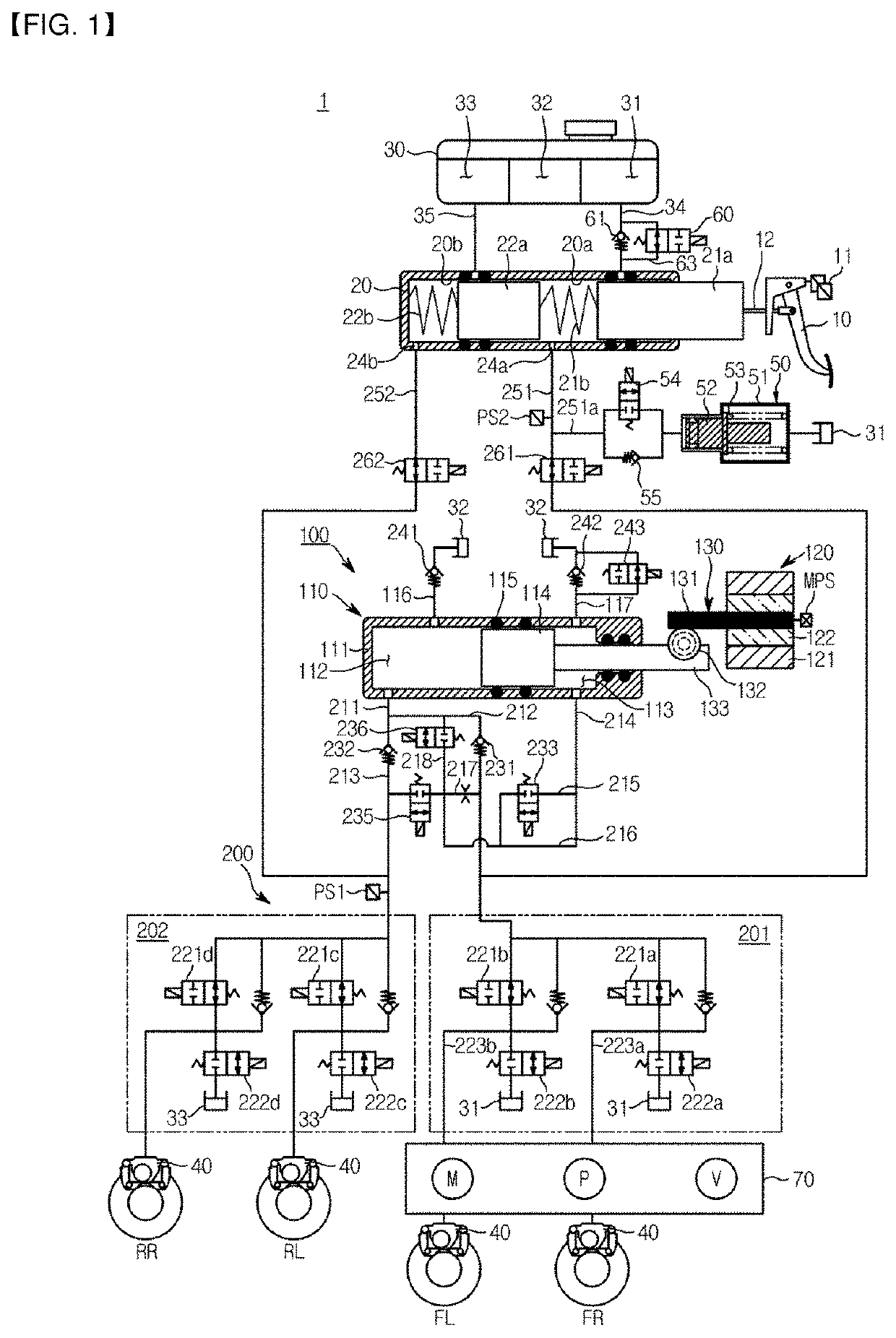
[0037]FIG. 1 is a hydraulic circuit diagram showing a non-braking state of an electronic brake system according to the present disclosure.

[0038]Referring to FIG. 1, an electronic brake system 1 typically includes a master cylinder 20 for generating a hydraulic pressure, a reservoir 30 coupled to an upper portion of the master cylinder 20 to store oil, an input rod 12 for pressing the master cylinder 20 in accordance with a pedal effort of the brake pedal 10, wheel cylinders 40 that receive the hydraulic pressure and perform braking of each of wheels FL, RR, RL, and FR, a pedal displacement sensor 11 for sensing the displacement of the brake pedal 10, and a simulation apparatus 50 for providing a reaction force in accordance with the pedal effort of the brake pedal 10.

[0039]The master cylinder 20 may be configured to include at least one chamber to generate hydraulic pressure. As an example, the master cylinder 20 may include a first master chamber 20a and a second master chamber 20b...

second embodiment

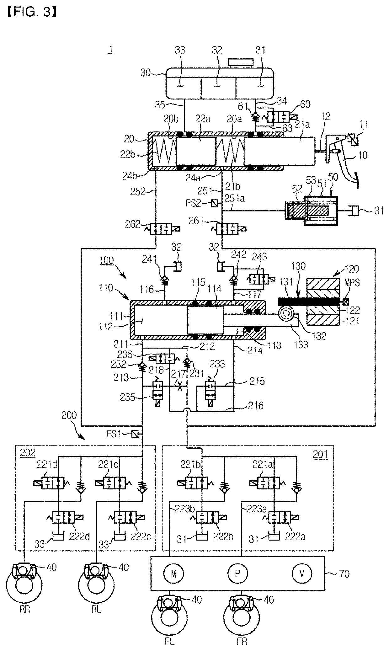
[0198]Referring to FIGS. 3 and 4, in the electronic brake system according to the present disclosure, a branch passage 251a provided with the pedal simulator may be directly connected to the first backup passage 251 and the reservoir 30 at any time without an electronic valve intervention.

[0199]By performing the fallback function of the redundancy control apparatus 70, the simulator valve 54 provided in the branch passage 251a of the electronic brake system according to the first embodiment of the present disclosure and the simulator check valve 55 connected to the simulator valve 54 in parallel are unnecessary. Therefore, the branch passage 251a may be directly connected to the first backup passage 251 and the reservoir 30 without an electronic valve intervention.

[0200]The operation of the pedal simulation apparatus 50 in the electronic brake system according to the second embodiment of the present disclosure will be described. when the driver provides the pedal effort to the brake...

third embodiment

[0202]Referring to FIGS. 5 and 6, in the electronic brake system according to the present disclosure, the first reservoir passage 34 may be directly connected to the reservoir 30 and the master cylinder 20 without an electronic valve intervention.

[0203]The redundancy control apparatus 70 performs the fallback function so that the inspection mode performed in the electronic brake system according to the first embodiment of the present disclosure is unnecessary. Therefore, the inspection valve 60, the check valve 61, and the bypass passage 63 provided in the first reservoir flow passage 34 may be eliminated for the inspection mode. That is, it is not necessary to check the leakage of the simulator valve 54 and the stuck failure of the second piston 22a of the master cylinder 20 because the redundancy control apparatus 70 performs the fallback function, so that the first reservoir passage 34 may be directly connected to the reservoir 30 and master cylinder 20 without an electronic valv...


PUM


Abstract

An electronic brake system of the present disclosure is disclosed. The an electronic brake system may include a reservoir to store oil: a master cylinder having a master piston connected to a brake pedal and a master chamber for discharging oil by a displacement of the master piston; a hydraulic pressure supply apparatus generating hydraulic pressure by an electrical signal output corresponding to a displacement of the brake pedal to supply to wheel cylinders of the respective wheels; a hydraulic control unit transmitting the hydraulic pressure discharged from the hydraulic pressure supply apparatus to the wheel cylinders of the respective wheels; and a redundancy control apparatus generating hydraulic pressure using a motor and a pump to transmit to at least one of the wheel cylinders.

Description

CROSS-REFERENCE TO RELATED APPLICATION(S)[0001]This application is based on and claims priority under 35 U.S.C. § 119 to Korean Patent Application No. 10-2018-0061582, filed on May 30, 2018, in the Korean Intellectual Property Office, the disclosure of which is incorporated herein by reference in its entirety.BACKGROUND1. Technical Field[0002]The present disclosure relates to an electronic brake system, and more particularly, to an electronic brake system that generates a braking force that generates a braking force in accordance with an electrical signal.2. Description of the Related Art[0003]In general, a vehicle is essentially equipped with a brake system for braking, and in recent years, various types of brake systems have been proposed to obtain a more powerful and stable braking force.[0004]For example, the brake system includes an anti-lock brake system (ABS) for preventing slippage of the wheels during braking operation, a brake traction control system (BTCS) for preventing ...

Claims


Application Information

Patent Timeline
Patent Type & Authority Applications(United States)
IPC IPC(8): B60T13/62B60T13/16B60T7/04B60T8/32B60T8/40
CPCB60T2270/82B60T2270/30B60T2270/402B60T8/326B60T8/4081B60T7/042B60T2270/404B60T2270/10B60T2270/413B60T13/62B60T13/167B60T13/142B60T8/409B60T13/745B60T13/662B60T13/146B60T13/686B60T17/22B60T13/148B60Y2400/81
Inventor JEONG, HYOJINLIM, EUN-SEONG
Owner HL MANDO CORP
Why Eureka
Try Eureka