Vertical cavity surface-emitting laser
a laser and vertical cavity technology, applied in semiconductor lasers, laser details, electrical devices, etc., can solve the problems of laser light noise, laser oscillation through a vertical cavity structure, etc., and achieve the effect of reducing relative intensity nois
- Summary
- Abstract
- Description
- Claims
- Application Information
AI Technical Summary
Benefits of technology
Problems solved by technology
Method used
Image

Examples
specific example 1
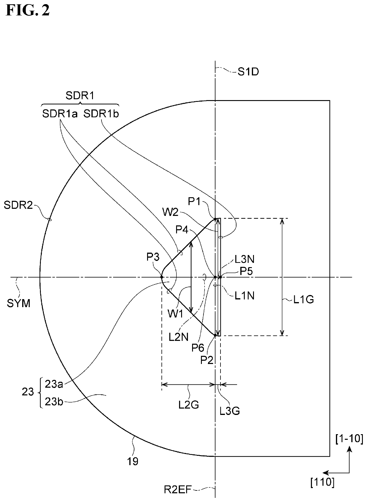
[0127]Referring to FIG. 9, the edge SDR1 of the current aperture region 23a and the edge SDR2 of the post structure 19 are shown in solid lines. The cross-section of the current aperture region 23a has a projecting shape defined by the edge SDR1.
[0128]The first reference plane R1EF crosses a second reference plane R2EF at a first reference line segment L1N. The second reference plane R2EF extends along the first axis AX1. The first line segment L1N join a first point P1 and a second point P2 on the edge SDR1 of the cross-section of the current aperture region 23a (the cross-section shown in FIG. 9). The edge SDR1 has a first portion SDR1a and a second portion SDR1b that are delimited by the first point P1 and the second point P2. In the vertical cavity surface-emitting laser 11 exemplified in Specific Example 1, the first to third line segments L1N, L2N and L3N satisfy with first to third conditions described bellow.
[0129]First Condition
[0130]The first reference line segment L1N ext...
specific example 2
[0145]Referring to FIG. 10, the edge SDR1 of the current aperture region 23a and the edge SDR2 of the post structure 19 are shown in solid lines. The cross-section of the current aperture region 23a has a projecting shape defined by the edge SDR1.
[0146]The first reference plane R1EF crosses a second reference plane R2EF at a first reference line segment L1N. The second reference plane R2EF extends along the first axis AX1. The first line segment L1N joins a first point P1 and a second point P2 on the edge SDR1 of the cross-section of the current aperture region 23a (the cross-section shown in FIG. 10). The edge SDR1 has a first portion SDR1a and a second portion SDR1b that are delimited by the first point P1 and the second point P2.
[0147]As shown in FIG. 10, the first reference line segment L1N meets the first condition of Specific Example 1. The first reference line segment L1N and the second reference line segment L2N meet the second condition of Specific Example 1.
[0148]In this e...
specific example 3
[0161]Referring to FIG. 11, the edge SDR1 of the current aperture region 23a and the edge SDR2 of the post structure 19 are shown in solid lines. The cross-section of the current aperture region 23a has a projecting shape defined by the edge SDR1.
[0162]The first reference plane R1EF crosses a second reference plane R2EF extending in the direction along the first axis Ax1 at a first reference line segment L1N. The first reference line segment L1N joins a first point P1 and a second point P2 on the edge SDR1 of the cross-section defined by the crossing of the first reference plane R1EF and the current aperture region 23a (the cross-section shown in FIG. 11). The edge SDR1 has a first portion SDR1a and a second portion SDR1b that are delimited by the first point P1 and the second point P2.
[0163]As shown in FIG. 11, the first reference line segment L1N meets the first condition. The first reference line segment L1N and the second reference line segment L2N meet the second condition. The...
PUM
 Abstract
Description
Claims
Application Information
PatSnap Eureka turns technology decisions into work you can execute. Powered by our Innovation Knowledge Graph, it runs expert workflows across engineering, life sciences, materials and intellectual property. Get your review-ready output in minutes.


