Image encoding apparatus, image decoding apparatus, control methods thereof, and non-transitory computer-readable storage medium

a technology of image encoding and decoding apparatus, applied in electrical apparatus, digital video signal modification, pictoral communication, etc., can solve problems such as the difficulty of recording raw data at a compact size, and achieve the effect of suppressing a drop in image quality

Active Publication Date: 2019-12-19
CANON KK
View PDF0 Cites 3 Cited by
  • Summary
  • Abstract
  • Description
  • Claims
  • Application Information

AI Technical Summary

Benefits of technology

[0005]Having been achieved in light of the above-described problem, the present invention provides a technique that, when dividing RAW image data into a plurality of tiles and encoding the data, enables the RAW data to be recorded at a compact size by suppressing the data amount of quantization parameters included in coded data, while suppressing a drop in image quality at tile boundaries and implementing lossy compression through flexible quantization control.
[0007]According to the present invention, when dividing RAW image data into a plurality of tiles and encoding the data, the RAW data can be recorded at a compact size by suppressing the data amount of quantization parameters included in coded data, while suppressing a drop in image quality at tile boundaries and implementing lossy compression through flexible quantization control.

Problems solved by technology

This makes it difficult to record the RAW data at a compact size while maintaining image quality that shows no loss visually.

Method used


Image

  • Image encoding apparatus, image decoding apparatus, control methods thereof, and non-transitory computer-readable storage medium
  • Image encoding apparatus, image decoding apparatus, control methods thereof, and non-transitory computer-readable storage medium
  • Image encoding apparatus, image decoding apparatus, control methods thereof, and non-transitory computer-readable storage medium

Examples


first embodiment

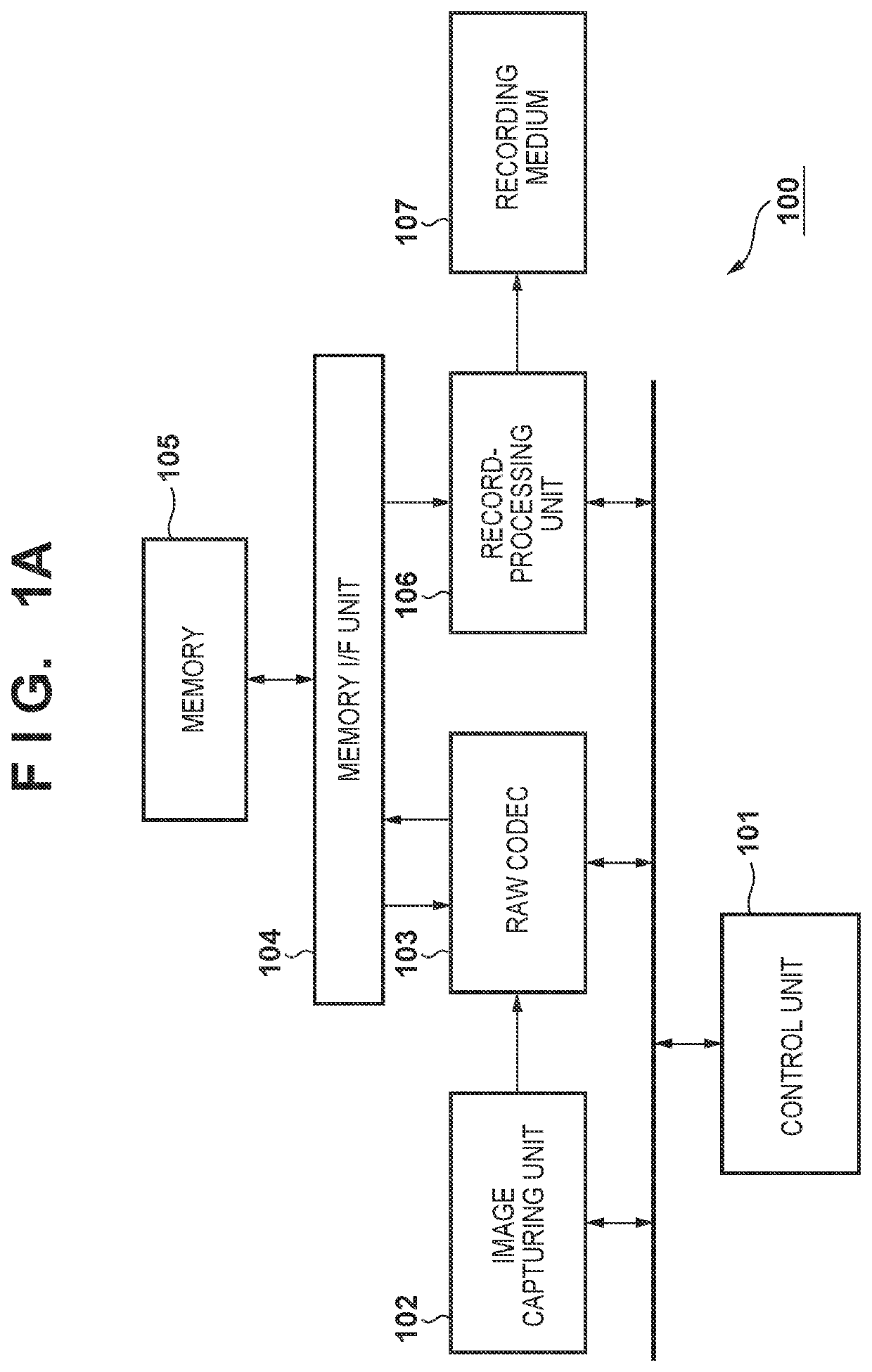
[0036]FIG. 1A is a block diagram illustrating the main configuration, pertaining to encoding, in an image capturing apparatus 100 according to an embodiment. The image capturing apparatus 100 can be realized as a digital camera or a digital video camera, for example. Aside from these, the image capturing apparatus 100 can also be realized as any information processing terminal or image processing apparatus, such as a personal computer, a mobile phone, a smartphone, a PDA, a tablet terminal, a mobile media player, or the like. FIG. 1A assumes a situation where the device functions as an image capturing apparatus, i.e. a digital camera or the like, and therefore illustrates a configuration that includes an image capturing unit 102. However, the present invention can be applied in an image encoding apparatus, an image decoding apparatus, an image recording apparatus, an image compression apparatus, an image restoring apparatus, or the like capable of recording and playing back RAW imag...

second embodiment

[0091]A second embodiment will be described next. The image capturing apparatus according to the present second embodiment can have the same configuration as the image capturing apparatus according to the first embodiment. However, the units for which the first quantization parameters are generated by the quantization parameter generating unit 203 of the RAW codec 103, and the process for generating the individual second quantization parameters for each channel and each sub-band, are different. Configurations that are the same as in the first embodiment will not be described in the present embodiment, with focus being given primarily to configurations pertaining to the different method of generating the quantization parameters.

[0092]FIG. 12A illustrates units for evaluating sub-band data pertaining to image quality control and updating quantization parameters in a case where each channel is divided into sub-bands at lev=3. The common first quantization parameters (QpBs) are generate...

third embodiment

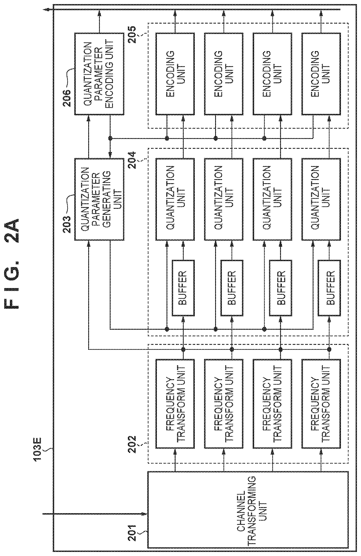
[0099]A third embodiment of the invention will be described next. FIG. 23A illustrates the configuration of the RAW data encoding unit 103E of an image capturing apparatus according to the present third embodiment, and FIG. 23B illustrates the configuration of the RAW data decoding unit 103D. The differences from FIGS. 2A and 2B are that a tile dividing unit 2301 has been added to the RAW data encoding unit 103E, and a tile merging unit 2302 has been added to the RAW data decoding unit 103D. The rest is assumed to be the same as in the second embodiment.

[0100]The tile dividing unit 2301 divides a single frame of input RAW image data into a pre-set number of tiles, and supplies the tiles one by one to the channel transforming unit 201. However, when supplying the RAW image data of a tile of interest obtained from the division to the channel transforming unit 201, the tile dividing unit 2301 according to the embodiment also supplies, to the channel transforming unit 201, pixel data lo...


PUM


Abstract

An encoding apparatus comprises a dividing unit that divides RAW image data into a plurality of tiles, a generating unit that generates planes of a plurality of channels having mutually-different components for each of the tiles, a transforming unit that frequency-transforms the plane of each channel and generates sub-band data of a plurality of resolution levels, a controller that divides each of the plurality of sub-band data into the same number of segments to divide the sub-band data into a plurality of segments corresponding to the same regions, and determines first quantization parameters common for the plurality of sub-band data in each segment, a quantizing unit that, based on the determined first quantization parameters, quantizes each sub-band data, and an encoder that encodes a quantization result on a sub-band-by-sub-band basis.

Description

BACKGROUND OF THE INVENTIONField of the Invention[0001]The present invention relates to image encoding technology.Description of the Related Art[0002]CCDs or CMOS image sensors are employed as image sensors in digital cameras, video cameras, and the like. When using a single-panel image sensor, green, blue, and red pixel data are obtained by employing a Bayer pattern color filter. A digital camera generates final image data by subjecting Bayer pattern green, blue, and red data (“RAW data” hereinafter) to developing processing including demosaicing processing, noise removal processing, optical distortion correction, color correction processing, and the like. Image data compressed using an encoding method such as JPEG (for still images) or H.264 (for moving images) is thus recorded into a recording medium. However, many image capturing apparatuses have functions for recording the RAW data before the data is subjected to the developing processing, so that the user can carry out his or ...

Claims


Application Information

Patent Timeline
Patent Type & Authority Applications(United States)
IPC IPC(8): H04N19/124H04N19/44H04N19/63
CPCH04N19/44H04N19/124H04N19/63H04N19/1883H04N19/154
Inventor TOGITA, KOJI
Owner CANON KK
Why Eureka
Try Eureka