Method and controller for actuator

Active Publication Date: 2019-12-26
NELES FINLAND OY
View PDF0 Cites 3 Cited by
  • Summary
  • Abstract
  • Description
  • Claims
  • Application Information

AI Technical Summary

Benefits of technology

The invention is a method and controller for controlling a pneumatic or hydraulic actuator of a process device. The method involves measuring the actuator pressure and using a simulation model to determine the position of the actuator or the process device. The controller can control the actuator based on the measured pressure or the simulated position, depending on the desired control mode. The invention allows for the accurate control of the actuator without the need for a position sensor, and can detect and address any failure in the position measurement. The technical effects of the invention include improved accuracy and efficiency in controlling pneumatic or hydraulic actuators, particularly in situations where a position sensor is not available.

Problems solved by technology

In both cases a failure in a valve position feedback, such as in the position sensor, may render the feedback control and the valve inoperative.
A disadvantage of this approach is that an additional secondary (pressure feedback) controller must be configured and tuned.

Method used


Image

  • Method and controller for actuator
  • Method and controller for actuator
  • Method and controller for actuator

Examples


Embodiment Construction

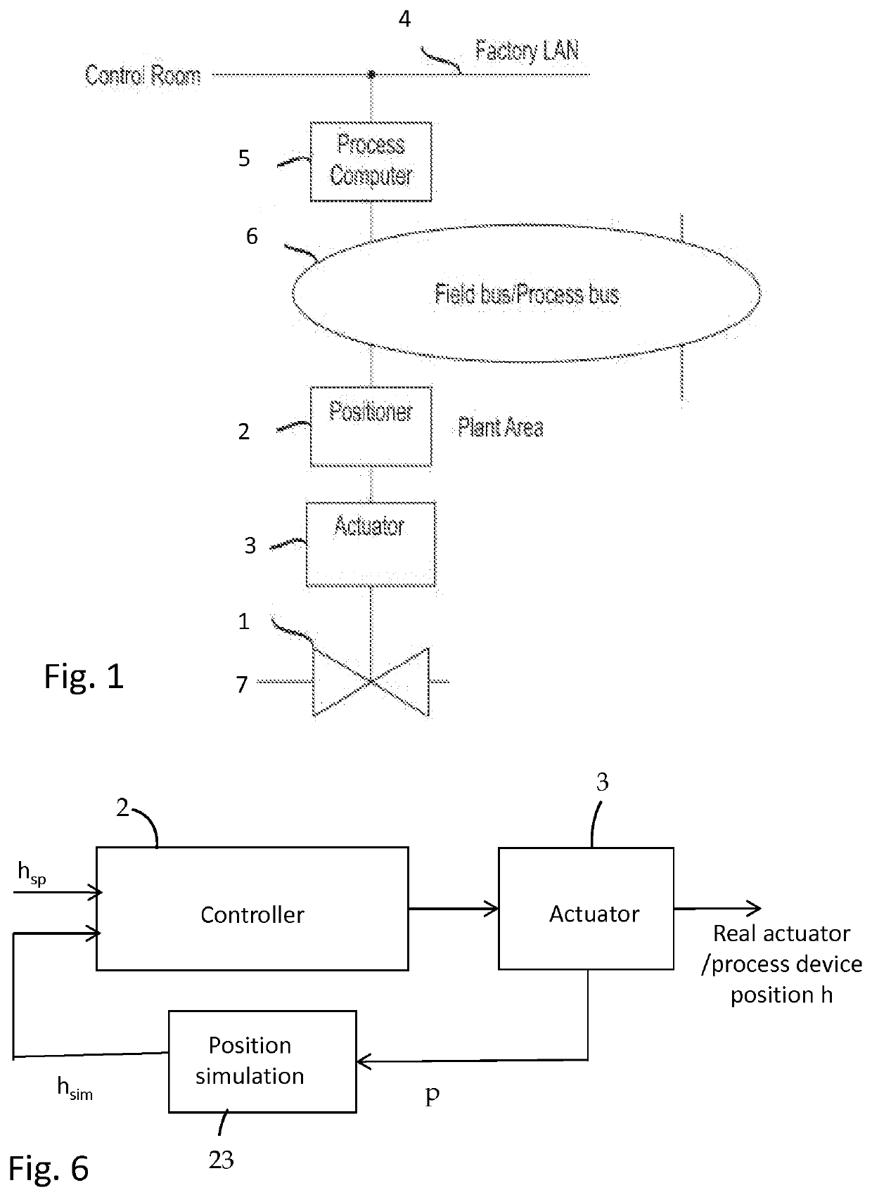
[0048]FIG. 1 shows a schematic block diaphragm of an exemplary process automation system wherein the principles of the invention may be applied in a valve positioner. The control system block 5 generally represents any and all control room computer(s) / programs and process control computer(s) / programs as well as databases, which may be interconnected by a factory LAN 4, in the automation system. There are various architectures for a control system. For example, the control system may be a Direct Digital Control (DDC) system or Distributed Control System (DCS), both well known in the art. It should be appreciated that the type or architecture of the automation system is not relevant to the present invention.

[0049]In the example of FIG. 1, a control valve assembly comprising a process valve 1 and a positioner 2 and an actuator 3 may be connected to a process to control the flow of a substance in a process pipeline 7. Material flows of a process or process pipeline may be controlled in ...


PUM


Abstract

A controller for controlling a pneumatic or hydraulic actuator of a process device includes a position feedback signal input for receiving a measured position signal representing a position of the actuator or the process device, an actuator pressure output, and a pressure sensor for measuring the actuator pressure. The controller is configured to operate in a measured position feedback mode and a simulated position feedback mode. In the measured position feedback mode the actuator is controlled dependent on a setpoint position and the measured position, and in the simulated position feedback mode the actuator is controller based on the setpoint position and a simulated position of the actuator or the process device. The simulated position is derived from the measured actuator pressure by a simulation model.

Description

FIELD OF THE INVENTION[0001]The invention relates to a control of actuators, particularly pneumatic and hydraulic actuators.BACKGROUND OF THE INVENTION[0002]Actuators are frequently used as mechanisms to introduce motion or control motion. It is operated by a source of energy, typically electric current, hydraulic fluid pressure, or pneumatic fluid pressure, and converts that energy into motion of a target mechanism, such as into movement of a closure element of a control valve.[0003]A control valve is generally used for a continuous control of a liquid or gas flow in different pipelines and processes. In a processing industry, such as oil and gas, mining, pulp and paper and chemical industries, different kinds of control valves installed in a plant's pipe system control material flows in the process. A material flow may contain any fluid material, such as fluids, liquors, liquids, gases and steam. The operation of a control valve involves positioning its movable or closing part (e....

Claims


Application Information

Patent Timeline
IPC IPC(8): F15B19/00
CPCF15B21/082F15B2211/6658F15B21/087F15B2211/6656F15B2211/6313F15B19/005F15B19/007G05B17/02G05B19/0426G05B2219/25312F15B2211/6336F15B2211/8636F15B2211/87F15B2211/8752G05B13/04G05B17/00G05B23/0235G05D3/12G05D7/0617
InventorFRIMAN, MATSHEIKKINEN, PASI
OwnerNELES FINLAND OY