
Arrangement And Method For Measuring The Performance Of Devices With Wireless Capability

Active Publication Date: 2019-12-26
BLUETEST
View PDF0 Cites 11 Cited by
  • Summary
  • Abstract
  • Description
  • Claims
  • Application Information

AI Technical Summary

Benefits of technology

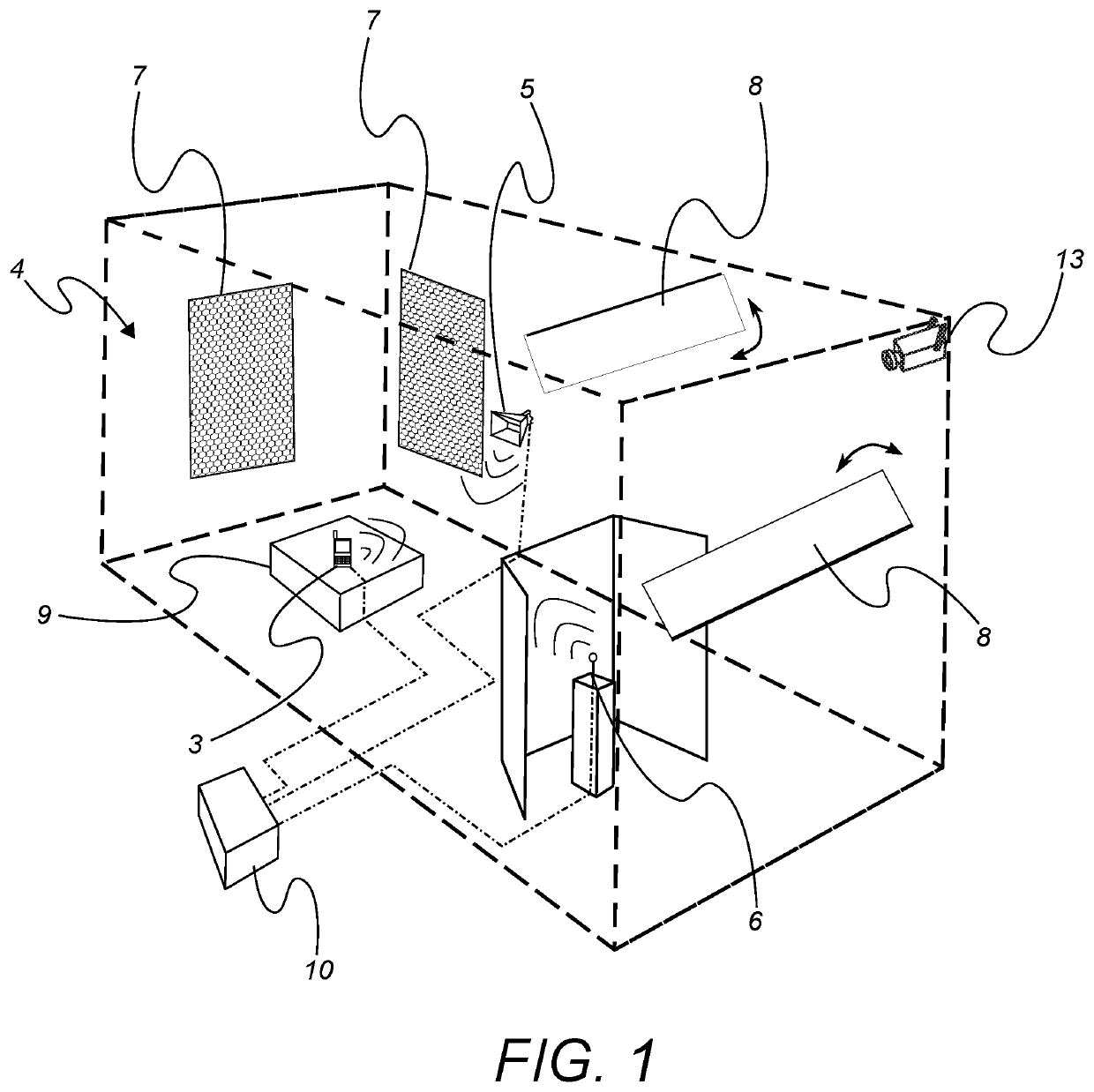
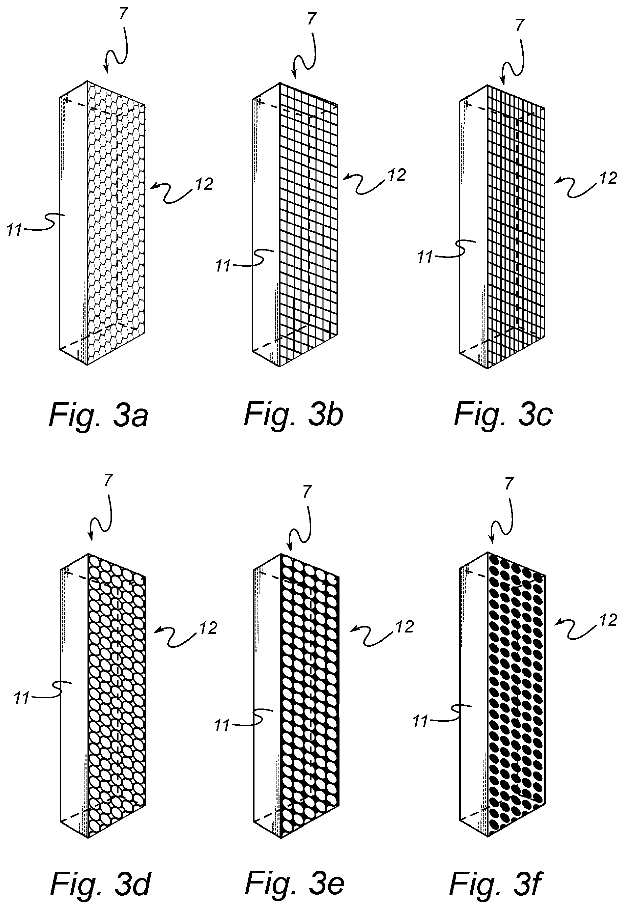
The present invention introduces a method and apparatus for characterizing the performance of mobile wireless terminals and their base station simulators. The invention includes a measurement arrangement that can measure transmission and reception performance of antennas, amplifiers, signal processing algorithms, and coding. The system is compatible for testing terminals for 5G networks. The invention also includes a cavity with separated antennas that can create a Rician fading environment and a shield to improve measurement accuracy. The electrically conductive grid with holes of predefined dimension can absorb effectively the electromagnetic signals transmitted by the first chamber antenna and create an environment close to a fully reverberant, high Q, high delay spread at low frequencies, and close to anechoic at higher frequencies.

Problems solved by technology

In more detail, in the next generation of mobile standards, devices will possibly be required to be able to both communicate at current frequency ranges 450 MHz-6 GHz and also at higher frequencies, in the range of, 6-100 GHz, which consequently will present new challenges in regards to testing of higher frequencies since the propagation properties of a wireless link is different at the higher frequencies, with less pronounced multipath.

Method used


Image

  • Arrangement And Method For Measuring The Performance Of Devices With Wireless Capability
  • Arrangement And Method For Measuring The Performance Of Devices With Wireless Capability
  • Arrangement And Method For Measuring The Performance Of Devices With Wireless Capability

Examples


Embodiment Construction

[0055]In the following detailed description, preferred embodiments of the present invention will be described. However, it is to be understood that features of the different embodiments are exchangeable between the embodiments and may be combined in different ways, unless anything else is specifically indicated. Even though in the following description, numerous specific details are set forth to provide a more thorough understanding of e present invention, it will be apparent to one skilled in the art that the present invention may be practiced without these specific details. In other instances, well-known constructions or functions are not described in detail, so as not to obscure the present invention.

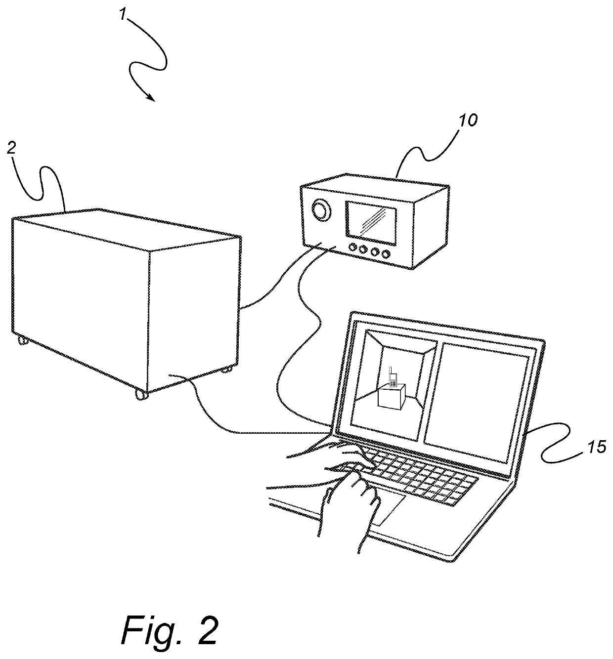
[0056]FIG. 1 shows an embodiment of a measurement arrangement 1 for measuring the performance of a device under test 3, such as antennas, mobile or wireless terminals, and specifically for antennas and terminals intended to be used in a multipath environment. The measurement arrangem...


PUM


Abstract

A new measurement arrangement and method for measuring the performance of a device under test, such as an antenna, a mobile phone and other wireless terminals, are disclosed. The chamber defines an internal cavity therein, adapted to enclose the device under test, and including walls of an inwardly reflective material, rendering the walls reflective to electromagnetic waves, thereby simulating a multi-path environment. Thus, the chamber is a reverberation chamber. Further, at least one first chamber antenna and at least one second chamber antenna, are arranged in the cavity, the first and second chamber antennas being configured to transmit and receive electromagnetic waves within a first predefined frequency range and within a second predefined frequency range, respectively. A measuring instrument is connected to the device under test and the chamber antennas, for measuring the transmission between them. Furthermore, a frequency selective absorber is arranged in the cavity, the frequency selective absorber being arranged to absorb electromagnetic waves having a frequency within the first predefined frequency range and reflect electromagnetic waves having a frequency within the second predefined frequency range. Hereby, a measurement arrangement capable of testing of devices having wireless capability according to coming mobile communication standards is presented.

Description

TECHNICAL FIELD OF THE INVENTION[0001]The present invention relates to an improved arrangement and method for measuring the performance of a device under test (DUT) having wireless capability. More specifically, the present invention relates to reverberation chambers.BACKGROUND[0002]The reverberation chambers, or mode-stirred chambers, have in recent years become effective tools in testing e.g. Over-the-Air performance of various wireless communication devices. Such chambers provide a straightforward solution to testing of devices that rely on multipath signal propagation for communication, often known as MIMO (Multiple Input Multiple Output) technologies, and for devices that simultaneously operate using several frequency bands, etc.[0003]The U.S. Pat. Nos. 7,444,264 and 7,286,961, by the same applicant, discloses such reverberation chambers useable to measure e.g. the radiation efficiency of antennas and the total radiated power (TRP) of mobile and wireless terminals such as cellu...

Claims


Application Information

Patent Timeline
Patent Type & Authority Applications(United States)
IPC IPC(8): G01R29/08H04B17/15H04B17/29
CPCG01R29/0821H04B17/29H04B17/15H04B17/10H04B17/20H04B17/19H04B17/3912H04W24/06H04B17/252
Inventor KVARNSTRAND, JOHN
Owner BLUETEST
Learn More