Miniaturized optical circulator

a circulator and optical technology, applied in the field of optical fiber communication technology, can solve the problems of hindering the market application of the device, wasting a large amount of optical fiber resources, and very large loss of optical signals, and achieves the effects of small optical components, reduced volume of existing optical circulators, and low cos

Active Publication Date: 2019-12-26
CHEN PEIJUAN
View PDF0 Cites 6 Cited by
  • Summary
  • Abstract
  • Description
  • Claims
  • Application Information

AI Technical Summary

Benefits of technology

[0021]The miniaturized optical circulator of the present invention has the following advantages over the conventional art: the present invention greatly reduces the volume of the existing optical circulator, making it possible to integrate in a small optical component. Meanwhile, the components and processes adopted in the invention are extremely mature and low in cost.

Problems solved by technology

If the output is not in the order of the specified port, the loss of the optical signal is very large, and the optical circulators have the effect of isolating optical signals.
The receiving and transmitting functions of the medium optical signal cause a waste of a large amount of optical fiber resources.
The above conventional is a typical representative optical circulator solution, but such a commercial optical ring type is bulky, and is difficult to be integrated into the same small optical component, which hinders the market application of the device.
In addition, the existing commercial optical circulators use more optical components, and the price is higher, which also limits their application.

Method used


Image

  • Miniaturized optical circulator
  • Miniaturized optical circulator
  • Miniaturized optical circulator

Examples


Embodiment Construction

[0028]In order to further understand the objects, structural features and functions of the present invention, the following detailed description will be made with reference to the accompanying drawings. It should be understood that the specific embodiments described in this section are merely illustrative of the invention and are not intended to limit the invention.

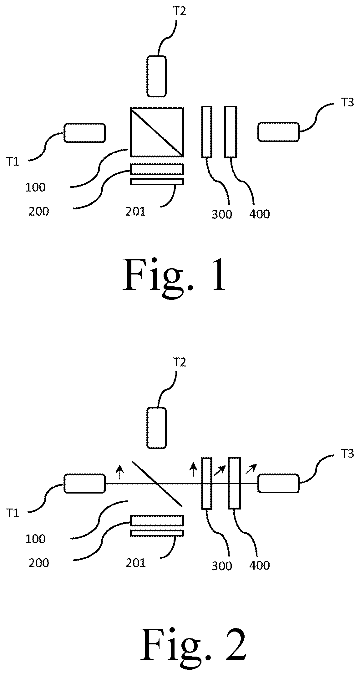
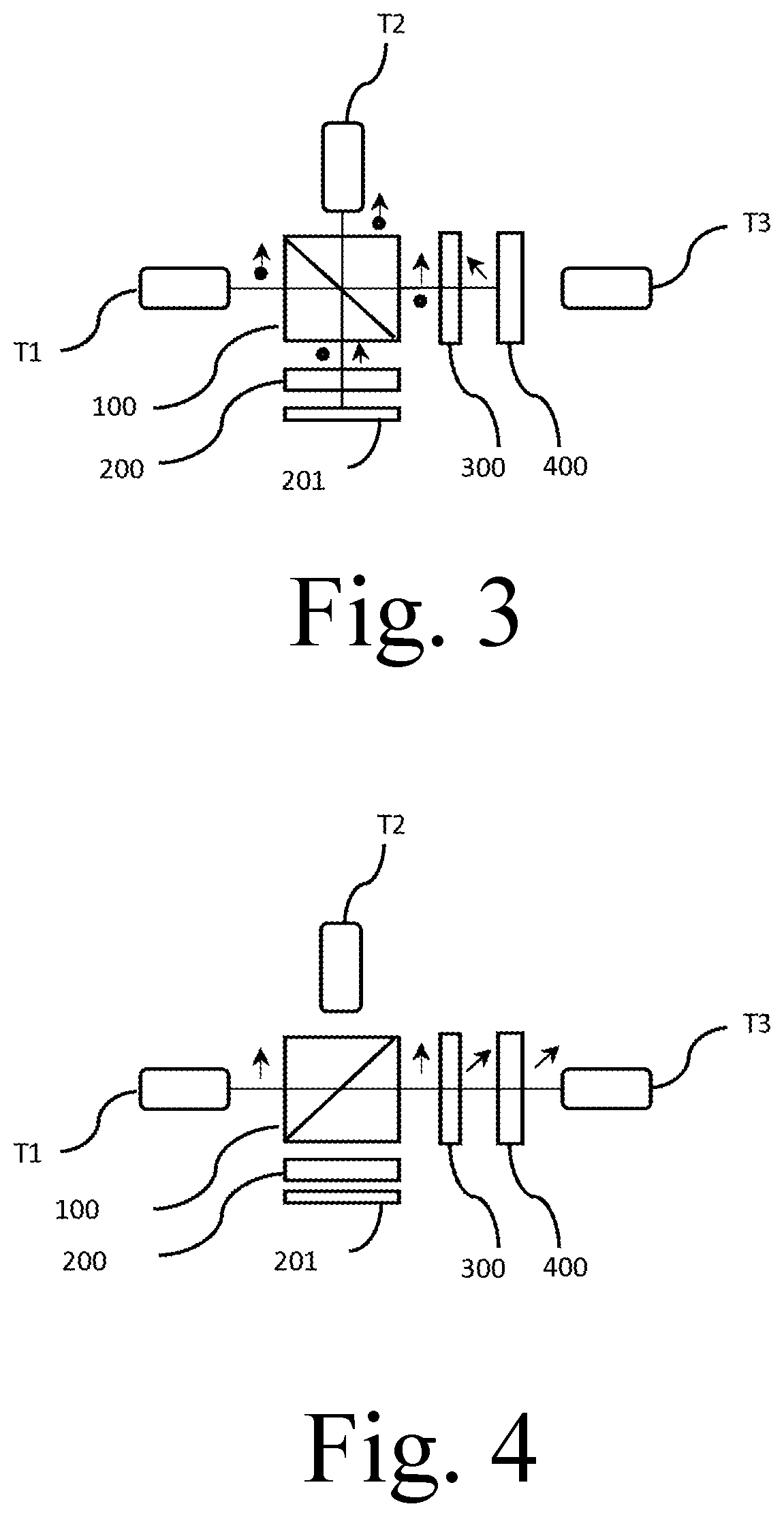
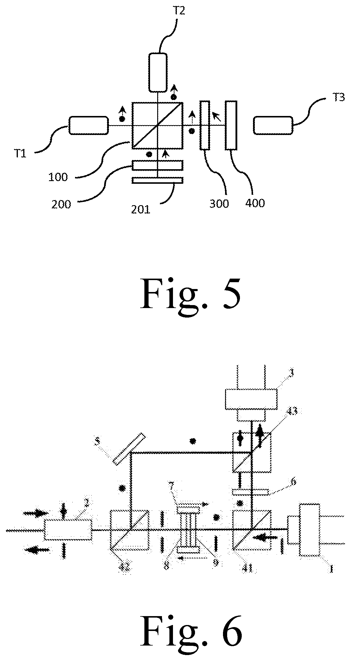
[0029]A miniaturized optical circulator of the present invention comprises: a common terminal, a receiving terminal, a transmitting terminal, and an optical component comprising a first polarized beam splitter, a reflective polarization controller, a 45-degree Faraday rotator and a second polarized beam splitter.

[0030]The function of the first polarized beam splitter is to separate the optical signal into a first polarization component and a second polarization component whose polarization directions are orthogonal to each other (without loss of generality, which can be assumed to be p-polarized light) and a second polari...


PUM


Abstract

A miniaturized optical circulator includes: two polarized beam splitters and a 45-degree Faraday rotator (300). An optical signal of a first optical path is input from a common terminal (T1) and then is separated into a first polarization component and a second polarization component by a first polarized beam splitter (100), the first polarization component first passes through the 45-degree Faraday rotator (300), reached a second polarized beam splitter (400) and then is reflected back, and at least successively passes through the 45-degree Faraday rotator (300) and the first polarization beam (100), and reached a receiving terminal (T2); the second polarization component at least under goes one reflection of the first polarized beam splitter (100) subsequent to being separated, and reaches the receiving terminal (T2); the optical signal of a second optical path is input from a transmitting terminal (T3), successively passes through the second polarized beam splitter (400), the 45-degree Faraday rotator (300), and the polarized beam splitter (100), and is output by the common terminal (T1). The optical circulator is small in volume and low in costs, and is easy to integrate.

Description

CROSS REFERENCE OF RELATED APPLICATION[0001]This is a U.S. National Stage under 35 U.S.C 371 of the International Application PCT / CN2017 / 111616, filed Nov. 17, 2017, which claims priority under 35 U.S.C. 119(a-d) to CN201611176985.9, filed Dec. 19, 2016; and to CN201621396439.1, filed on Dec. 19, 2016.BACKGROUND OF THE PRESENT INVENTIONField of Invention[0002]The present invention relates to the field of optical fiber communication technology, and more particularly to a miniaturized optical circulator.Description of Related Arts[0003]Optical circulators are commonly utilized in optical communication systems and optical measurement systems. The optical circulator is a multi-port input-output non-reciprocal optic device that allows optical signals to be transmitted only sequentially along a specified port, i.e when an optical signal is input from a specified port, it can only be output from another specific port. If the output is not in the order of the specified port, the loss of the...

Claims


Application Information

Patent Timeline
Patent Type & Authority Applications(United States)
IPC IPC(8): G02B27/28G02B6/27
CPCG02B6/2746G02B6/2706G02B27/286G02B27/283G02F1/09G02F1/093G02B5/30
Inventor CHEN, PEIJUAN
Owner CHEN PEIJUAN
Why Eureka
Try Eureka